
Installation Instructions


10
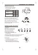
NOTE: The supply voltage must be consistent with the rate voltage of the air conditioner.
ELECTRICAL WORK
Model
Power supply
Input Rated Amp
(Switch/Fuse)
Power Cord Size
10A/15A
16A
2
>1.5mm
2
>1.0/1.5mm
220-240V~ 50Hz
or
220-230V~60Hz
12000Btu/h
12000Btu/h
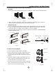
Connect the cable to the indoor unit
1. The inside and outside connecting cable can be connected without removing the front grille.
2. Connecting cable between indoor unit and outdoor unit shall be approved polychloroprene
sheathed flexible cord, type designation H07RN-F or heavier cord.
3. Lift the indoor unit panel up, remove the electrical box cover by loosening the screw.
4. Ensure the colour of wires of outdoor unit and the terminal Nos. are the same to the indoor s
respectively.
5. Wrap those cables not connected with terminals with insulation tapes, so that they will not touch
any electrical components. Secure the cable onto the control board with the cord clamp.
NOTE: Before performing any electrical work, turn off the main power to the system.
,
Electrical box
cover
Panel
Terminal block of indoor unit
To outdoor unit
To outdoor unit
Cord clamp
1 2(N) 3 4
1 2(N) 3 4
1
0
m
m
10
mm
40
m
m
40
m
m
Cooling only
type.
Cooling & heating
type.
Code wire
Fig.20
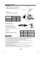
NOTE:
This indoor unit is especially designed to used as either MULTI modles or MONO modles.
Perform the following procedures to modify the indoor unit from MONO modles to MULTI modles
.(Fig.21 & 22)
1. Lift the indoor unit panel up, then remove the Electric control cover by loosen the screw(See Fig.20).
2. You will find a Slide Switch, printed with MONO and MULTI words beside(Fig.21).
3. Rip off the white paper above the Slide Switch and push it to the MULTI position(see Fig. 22).
4. Reinstall the Electric control cover, close the panel.And the indoor unit now can be used as
MULTI models.
MONO
MONO
MULTI
Rip off the
white paper
MONO
MONO
MULTI
MONO models MULTI models
Fig.21
Fig.22