
Installation Instructions
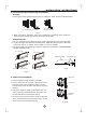


Open the valve stem until it hits against the stopper. Do not try to open it further.
Securely tighten the valve stem cap with aspanner or the like.
Valve stem cap tightening torque (See Tightening torque table in previous page ).
Outdoor
unit
Indoor
unit
Refrigerant
Flare nut
Stopper
Cap
Valve body
Packed valve
Half union
Gas side
Liquid side
A
C
D
B
Valve stem
Fig.24
Fig.25
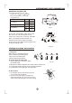
When Using the Vacuum Pump
(For method of using a manifold valve, refer to its operation manual.)
1. Completely tighten the flare nuts, A, B, C, D, connect the manifold valve charge
hose to a charge port of the low-pressure valve on the gas pipe side.
2. Connect the charge hose connection to the vacuum pump.
3. Fully open the handle Lo of the manifold valve.
4. Operate the vacuum pump to evacuate. After starting evacuation, slightly loose the
flare nut of the Lo valve on the gas pipe side and check that the air is entering
(Operation noise of the vacuum pump changes and a compound meter indicates
0 instead of minus)
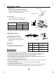
5. After the evacuation is complete, fully close the
handle Lo of the manifold valve and stop the
operation of the vacuum pump.
Make evacuation for 15 minutes or more and
check that the compound meter indicates
-76cmHg (-1x10 Pa).
o
6. Turn the stem of the packed valve B about 45
counterclockwise for 6~7 seconds after the gas
coming out, then tighten the flare nut again. Make
sure the pressure display in the pressure indicator
is a little higher than the atmosphere pressure.
7. Remove the charge hose from the Low pressure charge hose.
8. Fully open the packed valve stems B and A.
9. Securely tighten the cap of the packed valve.
Manifold valve
Compound meter
-76cmHg
Handle Lo
Handle Hi
Charge hose
Charge hose
Vacuum pump
Pressure gauge
Low pressure valve
Fig.26
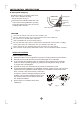
Caution in handling the packed valve
5
13
AIR PURGING