
Installation Instructions


4
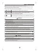
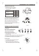
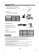
Accessories
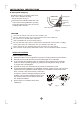
INSTALLATION INSTRUCTIONS
Note: Except the above parts provided, the other parts needed during installation you
must purchase.
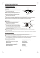
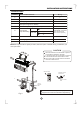
This illustration is for explanation purposes only.
Copper lines must be insulated independently
Fig.3
Use a stud finder to locate studs to prevent
unnecessary damage to the wall.
A minimum pipe run of 3 metres is required
to minimise vibration & excessive noise.
Two of the A, B and C directions should be
free from obstructions.
CAUTION
.
2
Seal (See Page 8 for details)
1
(See page 8 for details)
1
8
8
1
1
1
Self-tapping screw B
ST2.9x10-C-H
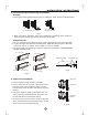
Remote controller
holder
8
9
Loop the
connective
cable.
C
B
A
60cm
above
6
0c
m a
bo
ve
30cm
abov
e
200cm ab
ove
6
12cm above
Air Filter
Air Outlet
30cm
abov
e
12cm
above
15cm above
1
2
3
Remote Controller
7
2
.
0m
a
b
o
v
e
Self-tapping Screw B ST2.9X10
Remote controller
Installation Plate
Name of Accessories
Self-tapping Screw A ST3.9X25
Drain Joint
Connecting
pipe Assembly
Clip Anchor
Number
Qty
Remote controller holder
Parts you must
purchase (A minimum
pipe wall-thickness
of 0.7mm is required.)
6.35
9.52
12.7
Liquid side
Gas side
( 12000Btu/h model)
( 12000Btu/h model)
1
2
3
4
5
6
7
8
9
ADJUST
AUTO
COOL
DRY
HEAT
FAN
HIGH
MED
LOW
MODE
FAN SPEED
DIRECTION
/SWING
TIMER ON
SLEEP
ON/OFF
TIMER OFF
SELF
CLEAN
RESET LOCK
SET TEMPERATURE( C)
FOLLOW
ME
LED
DISPLAY
CLEAN
AIR
TURBO