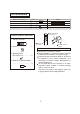
INSTALLATION MANUAL AIR CONDITIONER CEILING AND FLOOR TYPE For correct installation, read this manual before starting installation. This manual may be subject to change without notice for purpose of improvement.
CONTENT Installation precaution...........................................................................1 Installation place......................................................................................1 Accessories..................................................................................................3 Indoor unit installation..........................................................................4 Outdoor unit installation..............................................................
INSTALLATION PRECAUTION To install properly, please read this manual at first. The air conditioner must be installed by qualified persons. When installing the indoor unit or its tubing, please follow this manual as strictly as possible. When all the installation work is finished, please turn on the power only after a thorough check. No further announcement if there is any change of this manual caused by product improvement.
e. In buses or cabinets. f. In kitchen where it is full of oil gas. g. There is strong electromagnetic wave existing. h. There are inflammable materials or gas. i. There is acid or alkaline liquid evaporating. j. Other special conditions. Notes Before Installation 1. Select the correct carry-in path. 2. Move this unit as originally packaged as possible. 3.
ACCESSORIES Name of Accessories Owner's manual Installation manual Hook Hanging arm Q'ty 1 1 2 2 Qutline Usage (This manual) For wall mounting installation For ceiling installation 3 Mounting screw B ST2.9x10-C-H Remote controller & Its Frame 1. Remote controller..................1 1 Remote controller 2 Remote controller holder 2. Frame...................................1 Cautions on remote controller installation 3. Mounting screw (ST2.9x10-C-H).....................2 4.
INDOOR UNIT INSTALLATION Installing f10 hanging screw bolts. (4 bolts) Please refer to the following figure for the distance measurement between the screw bolts. Please install with f10 hanging screw bolts. The handling to the ceiling varies from the constructions, consult the construction personnels for the specific procedures. 1. The size of the ceiling to be handled ... ... do keep the ceiling flat. Consolidate the roof beam for possible vibration. 2. Cut off the roof beam. 3.
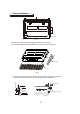
Wall Mounting Installtion D. Connecting point of refrigerant pipe (D. gas side) Drain point E. Connecting point of refrigerant pipe (E. Liquid side) Hook Chart 5 1.Fix the hook with tapping screw onto the wall.(Refer to Chart 6) Hook Tapping screw Washer <6mm Chart 6 2.Hang the indoor unit on the hook.
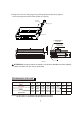
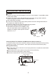
Ceiling Installation Hanging arm Chart 7 1.Remove the side board and the grille.(Refer to Chart 8) (For models 48000 and 60000 Btu/h, do not remove the grille.) Side board Grille Chart 8 8 13mm Screw nut 20 25mm 2.Locate the hanging arm on the hanging screw bolt.(Refer to Chart 9) Prepare the mounting bolts on the unit.( Refer to Chart 10) Washer Hanging screw bolt Mounting bolt(max.
3.Hang the unit on the hanging arm by sliding backward. Securely tighten the mounting bolts on both sides.(Refer to Chart 9) Hanging screw bolt Hanging arm Mounting bolt D. Connecting point of refrigerant pipe (D.gas side) E. Connecting point of refrigerant pipe (E. Liquid side) Drain point Chart 11 ATTENTION: The figures above are based on model with 18000Btu/h as rated capacity, which may differ from the unit you purchased.
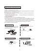
OUTDOOR UNIT INSTALLATION Caution Strong wind Keep this unit away from direct radiation of the sun or other heaters. If unavoidable, please cover it with a shelter. In places near coast or with a high attitude where the wind is strong, please install the outdoor unit against the wall to ensure normal performance. Use a baffle when necessary. In the case of extremely strong wind, please prevent the air from flowing backwards into the outdoor unit.
>60cm Please fasten the feet of this unit with bolts firmly to prevent it from collapsing in case of earthquake or strong wind. Make concrete foundation. (Refer to chart 14) Obstacle Fix with bolt Deep foundation Necessary width Chart 14 INSTALL THE CONNECTING PIPE Check whether the height drop between the indoor unit and outdoor unit, the length of refrigerant pipe, and the number of the bends meet the following requirements: The max height drop.......................................................
Cautions Daub the surfaces of the flare pipe and the joint nuts with frozen oil, and wrench it for 3~4 rounds with hands before fasten the flare nuts. (Refer to chart 14) Be sure to use two wrenches simultaneously when you connect or disconnect the pipes. 2) The stop valve of the outdoor unit should be closed absolutely (as original state). Every time you connect it, first loosen the nuts at the part of stop valve, then connect the flare pipe immediately (in 5 minutes).
CONNECT THE DRAIN PIPE 1. Install indoor unit drain pipe The outlet has PTI screw bread, Please use sealing materials and pipe sheath (fitting) when connecting PVC pipes. CAUTIONS The drain pipe of indoor unit must be heat insulated, or it will condense dew, as well as the connections of the indoor unit. Hard PVC binder must be used for pipe connection, and make sure there is no leakage. With the connection part to the indoor unit, please be noted not to impose pressure on the side of indoor unit pipes.
WIRING Attaching wiring 1. The air conditioner should use separate power supply with rated voltage 2. The external power supply to the air conditioner should have ground wiring, which is linked to the ground wiring of the indoor and outdoor unit. 3. The wiring work should be done by qualified persons according to circuit drawing. 4. A leakage protector should be installed according to the National Standard concerning electrical appliance. 5.
18000Btu/h 24000-36000Btu/h 24000-30000Btu/h 36000-60000Btu/h (Cooling& Heating) (Cooling& Heating) (Cooling& Heating) (Cooling& Heating) TYPE(for R407C) PHASE POWER 1-PHASE FREQUENCY AND VOLT CIRCUIT BREAKER/FUSE (A) 2 INDOOR UNIT POWER WIRING(mm ) INDOOR/OUTDOOR CONNECTING WIRING 2 (mm ) GROUND WIRING OUTDOOR UNIT POWER WIRING STRONG ELECTRIC SIGNAL WEAK ELECTRIC SIGNAL PHASE POWER CIRCUIT BREAKER/FUSE (A) 2 INDOOR UNIT POWER WIRING(mm ) INDOOR/OUTDOOR CONNECTING WIRING 2 (mm ) GROUND WIRING
12000~18000Btu/h 24000-36000Btu/h (Cooling Only) (Cooling Only) TYPE(for R22) POWER PHASE 1-PHASE FREQUENCY AND VOLT 220-240V~, 50Hz CIRCUIT BREAKER/FUSE (A) 2 INDOOR UNIT POWER WIRING(mm ) INDOOR/OUTDOOR CONNECTING WIRING GROUND WIRING OUTDOOR UNIT POWER WIRING STRONG ELECTRIC SIGNAL WEAK ELECTRIC SIGNAL 2 (mm ) 1-PHASE 3-PHASE 220-240V~, 50Hz 380V 3N~, 50Hz 20/16 40/25 40/20 3x2.5 3x2.5 5x2.5 2.0 2.5 2.5 3x2.5 5x2.5 1X2.0 1X2.0 3X2.0 1-core sheild wire 2 1x0.
CAUTION: When wiring, please choose the corresponding chart, or it may cause damage.
A B C N 1 2 3 POWER 380V 3N~ 50Hz 5-core cable 5*2.5mm2 1 2 3 4 5-core cable 5*2.5mm2 A B C N 3-core cable 3*1.5mm2 36000-60000Btu/h (3 PHASE) Air Conditioner Link-circuit (For R410a,R407c and R22,Cooling& Heating) Chat 22 220-240V~ 50Hz 3-core cable 3 2.5mm 2 2 3-core cable 3 2.
220-240V~ 50Hz 1-core cable 1 2.0mm 2 3-core cable 3 2.5mm 2 2 3-core cable 3 2.5mm 24000Btu/h (1 PHASE) Air Conditioner Link-circuit (For R410a,Cooling Only) Chat 24 380V 3N~ 50Hz 5-core cable 5 2.5mm 2 2 5-core cable 5 2.5mm 1-core cable 1 2.
220-240V~ 50Hz 3-core cable 3 2.5mm 2 2 3-core cable 3 2.
~ 24000-36000Btu/h(1 PHASE) Air Conditioner Link-circuit (For R22,Cooling &Heating) Chat 28 220-240V~ 50Hz 2 1-core cable 1 2.5mm 3-core cable 3 2.5mm 2 2 3-core cable 3 2.
~ 30000~36000Btu/h (1 PHASE) Air Conditioner Link-circuit (For R407c,Cooling& Heating) Chat 30 ~ 24000-30000Btu/h(3 PHASE) Air Conditioner Link-circuit (For R407c,Cooling only ) Chat 31 20
~ 24000-30000Btu/h(3 PHASE) Air Conditioner Link-circuit (For R407c,Cooling &Heating) Chat 32 2 2-core cable 2 2.0mm 220V~ 60Hz 3-core cable 3 N mm 220V~ 60Hz 3-core cable 3 N mm2 24000-48000Btu/h(1 PHASE) Air Conditioner Link-circuit (For R22,Cooling only ) Chart 33 21 2 NOTE: 36000Btu/h 36000Btu/h N=2.5 N=4.
220-240V~ 50Hz 3-core cable 3 2.5mm 2 2 3-core cable 3 2.0mm 12000Btu/h (1 PHASE) Air Conditioner Link-circuit (For R22 ,Cooling Only ) Chat 34 The Outdoor Units Disassemble the bolts from the maintenance board, and pull it in the direction of the arrow to remove the protection board. Notice: Do not scratch the surface during operation. ATTENTION: Chart 35 is based on one type of outdoor units, which may look different from your own outdoor unit.
TEST OPERATION 1. The test operation must be carried out after the entire installation has been completed. 2. Please confirm the following points before the test operation: The indoor unit and outdoor unit are installed properly. Tubing and wiring are correctly completed. The refrigerant pipe system is leakage-checked. The drainage is unimpeded. The heating insulation works well. The ground wiring is connected correctly.
MDV05I-011fW 2200017207