
User's Manual
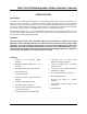
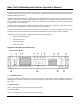
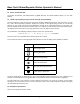
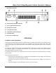

Table Of Contents
- Description
- Attention
- Features
- Controls, Indicators and Connectors
- _
- Front Panel Controls
- _
- Headphone Socket
- High TX Power
- Low TX Power
- Loud Speaker*
- Repeater Mode Indicator LED
- 6. Alarm Mode Indicator LED
- 7. Transmit Mode Indicator LED
- 8. Busy Mode Indicator LED
- 9. Keypad*
- 10. Volume Control*
- 11. Squelch Control*
- 12. Power ON/OFF Switch
- 13. Power On Indicator LED
- 14. Liquid Crystal Display (LCD) (not used on Single Channel Models)
- Symbol
- _
- Rear Panel Connectors
- Front Panel Controls
- _
- Installation and Programming
- Basic Operation
- Front Panel Operation
- Signaling
- Scanning
- Locking the Keypad
- Changing Tone Signaling Systems
- Displaying the Channel Information
- Display of Received Tone Frequencies.
- Bar Graph Displays
- LCD Display Back Light
- Transmit Power Change
- Calling Party ID Display
- Displaying any Radio's ID Number
- Emergency Caller Display
- Automatic Transmit in Repeater Mode
- TX Test Mode
- Keypad Test Mode
- Frequency Band Test Mode
- Starting Message
- Serial Number Display
- EEROM Data Check Mode
- Hardware Error Detection
- RS232C Communications Error

Base Tech II Base/Repeater Station Operator’s Manual
4
The Base Tech II Base Repeater includes 5-tone selective calling encoder/decoder with non-predictive decoder,
as well as a DTMF encoder and voice encryption option. It supports both all channel scanning and programmed
channel scanning for base use.
The Base Tech II Base Repeater is fitted with a large full dot matrix LCD that is used to display the channel
numbers and names, frequency and tone programmed information and signaling information. All user-interface
keys and knobs are conveniently located on the front of the radio. All user-entered functions are easily activated
in a logical manner via the keypad.
The Base Tech II Base Repeater is supplied with an "N" type connector for the transmitter, and a BNC connector
for the receiver to allow easy connection to the duplexer or feeder cables.
The rear panel includes a 9-way D-sub connector for the attachment of an external shared tone panel. Also
included is a 25-way D-sub connector that enables external interface to other radios or control equipment.
The Base Tech II Base Repeater is supplied complete with the following items:
o Base Tech II Base Repeater
o DC Cable Connector
o Operators Manual
o Hand Microphone
Controls, Indicators and Connectors
•
Front Panel Controls
1. Headphone Socket
This socket is provided to allow users to listen to the Base Tech II Base Repeater using headphones. Plugging a
headphone into this socket will disconnect the built-In speaker. It does NOT include a microphone input or TX
PTT facility.
2. High TX Power
This is a service point and is not used by the radio operators
3. Low TX Power
This is a service point and is not used by the radio operators