
User's Manual
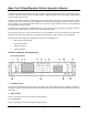
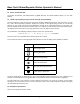
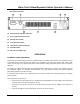

Table Of Contents
- Description
- Attention
- Features
- Controls, Indicators and Connectors
- _
- Front Panel Controls
- _
- Headphone Socket
- High TX Power
- Low TX Power
- Loud Speaker*
- Repeater Mode Indicator LED
- 6. Alarm Mode Indicator LED
- 7. Transmit Mode Indicator LED
- 8. Busy Mode Indicator LED
- 9. Keypad*
- 10. Volume Control*
- 11. Squelch Control*
- 12. Power ON/OFF Switch
- 13. Power On Indicator LED
- 14. Liquid Crystal Display (LCD) (not used on Single Channel Models)
- Symbol
- _
- Rear Panel Connectors
- Front Panel Controls
- _
- Installation and Programming
- Basic Operation
- Front Panel Operation
- Signaling
- Scanning
- Locking the Keypad
- Changing Tone Signaling Systems
- Displaying the Channel Information
- Display of Received Tone Frequencies.
- Bar Graph Displays
- LCD Display Back Light
- Transmit Power Change
- Calling Party ID Display
- Displaying any Radio's ID Number
- Emergency Caller Display
- Automatic Transmit in Repeater Mode
- TX Test Mode
- Keypad Test Mode
- Frequency Band Test Mode
- Starting Message
- Serial Number Display
- EEROM Data Check Mode
- Hardware Error Detection
- RS232C Communications Error

Base Tech II Base/Repeater Station Operator’s Manual
6
13. Power On Indicator LED
The Power ON Indicator LED will illuminate in
green
whenever the Power ON/OFF switch is in the "ON"
position.
14. Liquid Crystal Display (LCD) (not used on Single Channel Models)
The LCD comprises of four (4) lines each of which is capable of displaying twenty-one (21) characters. The first
line, under normal operating conditions, displays the strength of the signal being received on the selected
channel as a bar graph. The second line displays the strength of the transmitting power as a bar graph. The
third line displays the selected channel number (up to four characters) in the first five left hand character spaces,
and displays the channel name (up to eight characters) in the next eight character spaces.
Any combination of the following characters may be used in the channel name:
0-9, A-Z, a-z, / + - * # ! $ % ( ) = [ ] < > ? and space
This area of the LCD is left blank when channel names are not used.
The six character spaces on the right hand side of this line are used to display status symbols as follows:
Symbol Status
The monitor status.
The key lock status.
The tone encode status.
The scan mode status.
The high power transmit status.
[SHIFT] key is depressed.
On the left hand side of the fourth line, the type of tone signaling system selected by the user is displayed. For
example, "5TON" indicates 5 Tone signaling while “DTMF” indicates Dual Tone Multi Frequency signaling.
The right hand side of the fourth line is used to display data that the user enters (for example, 5 Tone calling
sequences). These character spaces are also used by the Base Tech II Base Repeater to display messages
and information directed to the user.
15. Microphone Input Socket
Connect the microphone into this socket.