
User's Manual
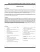
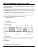
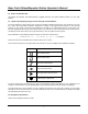
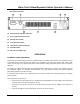

Table Of Contents
- Description
- Attention
- Features
- Controls, Indicators and Connectors
- _
- Front Panel Controls
- _
- Headphone Socket
- High TX Power
- Low TX Power
- Loud Speaker*
- Repeater Mode Indicator LED
- 6. Alarm Mode Indicator LED
- 7. Transmit Mode Indicator LED
- 8. Busy Mode Indicator LED
- 9. Keypad*
- 10. Volume Control*
- 11. Squelch Control*
- 12. Power ON/OFF Switch
- 13. Power On Indicator LED
- 14. Liquid Crystal Display (LCD) (not used on Single Channel Models)
- Symbol
- _
- Rear Panel Connectors
- Front Panel Controls
- _
- Installation and Programming
- Basic Operation
- Front Panel Operation
- Signaling
- Scanning
- Locking the Keypad
- Changing Tone Signaling Systems
- Displaying the Channel Information
- Display of Received Tone Frequencies.
- Bar Graph Displays
- LCD Display Back Light
- Transmit Power Change
- Calling Party ID Display
- Displaying any Radio's ID Number
- Emergency Caller Display
- Automatic Transmit in Repeater Mode
- TX Test Mode
- Keypad Test Mode
- Frequency Band Test Mode
- Starting Message
- Serial Number Display
- EEROM Data Check Mode
- Hardware Error Detection
- RS232C Communications Error

Base Tech II Base/Repeater Station Operator’s Manual
7
•
Rear Panel Connectors
16. 25 way External Options Connector
17. 9 way Programming Connector
18. DC Input Fuse Holder
19. 3 way DC Input Socket
20. TX/Antenna Connector (N type)
21. Ventilation Slots
22. RX Connector (BNC type)
OPERATION
Installation and Programming
As the Base Tech II Base Repeater can be installed to operate as either a Base Station or as a Repeater, some
of the instructions in this document may apply to one application only, some may apply in both cases, while
others may only apply if the particular function has been enabled during programming of the Base Tech II Base
Repeater.
The Base Tech II Base Repeater must be programmed before it will operate correctly. This should be done by
the equipment supplier or a qualified radio tradesman. They will require the Base Tech II Base Repeater
programming software to do this correctly.
It is important that the Base Tech II Base Repeater be correctly installed at its working location by a qualified
radio technician.
As a minimum, it is necessary to:
o Connect the DC Input power lead to a suitable 13.8 Volt Regulated DC Power supply that has sufficient
capacity. (Ensure that the DC Polarity is correct).
o Connect the two antenna connectors to suitable antennas (ensure that the VSWR of the antennas is
correct).
o Insert the microphone into the microphone connector on the front panel.