
User's Manual
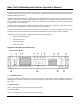
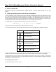
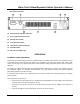

Table Of Contents
- Description
- Attention
- Features
- Controls, Indicators and Connectors
- _
- Front Panel Controls
- _
- Headphone Socket
- High TX Power
- Low TX Power
- Loud Speaker*
- Repeater Mode Indicator LED
- 6. Alarm Mode Indicator LED
- 7. Transmit Mode Indicator LED
- 8. Busy Mode Indicator LED
- 9. Keypad*
- 10. Volume Control*
- 11. Squelch Control*
- 12. Power ON/OFF Switch
- 13. Power On Indicator LED
- 14. Liquid Crystal Display (LCD) (not used on Single Channel Models)
- Symbol
- _
- Rear Panel Connectors
- Front Panel Controls
- _
- Installation and Programming
- Basic Operation
- Front Panel Operation
- Signaling
- Scanning
- Locking the Keypad
- Changing Tone Signaling Systems
- Displaying the Channel Information
- Display of Received Tone Frequencies.
- Bar Graph Displays
- LCD Display Back Light
- Transmit Power Change
- Calling Party ID Display
- Displaying any Radio's ID Number
- Emergency Caller Display
- Automatic Transmit in Repeater Mode
- TX Test Mode
- Keypad Test Mode
- Frequency Band Test Mode
- Starting Message
- Serial Number Display
- EEROM Data Check Mode
- Hardware Error Detection
- RS232C Communications Error

Base Tech II Base/Repeater Station Operator’s Manual
9
Front Panel Operation
This section describes most signaling and other advanced features that are available on the Base Tech II Base
Repeater. The availability of some features is dependent on the programming of the transceiver and installed
options. You may find it worthwhile to discuss these features in detail with your radio supplier to obtain a full
understanding of their benefits.
•
Keypad Operation
The Keypad is the interface between the user and the Base Tech II Base Repeater. It is used to enable or
disable various functions and to enter the required data for signaling purposes.
The word (5-Tone) or (DTMF) shown after the described feature indicates that the described feature applies to
the particular signaling format.
The following keys are used for the purposes described:
[0] - [9] Entering new channel numbers
Entering the "KILL" password
Entering signaling encoding numbers (5-Tone) (DTMF)
Entering DTMF numbers (DTMF)
[A] Advancing the Base Tech II Base Repeater to the next higher channel
Entering the signaling "A" tone (5-Tone) (DTMF)
Encodes the "A" Tone (DTMF)
[B] Advancing the Base Tech II Base Repeater to the next lower channel
Entering the signaling "B" tone (5-Tone) (DTMF)
Encodes the "B" Tone (DTMF)
[C] Entering the signaling "C" tone (5-Tone) (DTMF)
Encodes the "C" Tone (DTMF)
[D] Entering the signaling "D" tone (5-Tone) (DTMF)
Encodes the "D" Tone (DTMF)
[
•
] Displays the previously entered encode numbers (5-Tone) (DTMF)
Encodes the "
•
" -Tone (DTMF)
[#] Encodes the signaling numbers that are displayed in the LCD display (5-Tone) (DTMF)
Encodes the "#"-Tone (DTMF)
[CH] Used with two channel numbers [0] - [9] to change the active channel on the Base Tech II
Base Repeater. E.g. [CH]+[9]+[0] will change the active channel to Channel 90 (provided Ch
90 has been programmed into the Base Tech II Base Repeater.
[SCN] Used to place the Base Tech II Base Repeater into the "All-Scan" mode where the Base Tech
II Base Repeater will scan all programmed channels. Pressing the [SCN] key again will
cause the Base Tech II Base Repeater to exit from the "All-Scan" mode.
[MON] Switches the Base Tech II Base Repeater between "Monitor ON" mode and "Monitor OFF"
mode and is used to "Un-mute" the radio when using selective calling (depending on the
programming of the Base Tech II Base Repeater).