
User's Manual


KYODO KG510 OPERATORS MANUAL
128113 Page #5 of 26 Pages 11 December, 2000
2.3 Standard Inclusions
The KG510 transceiver is supplied complete with the following items:
KG510 transceiver
DC Cable
Operators Manual
KD561 Hand Microphone
3.0 CONTROLS, INDICATORS, & CONNECTORS
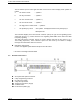
3.1 Front Panel Controls
1.
1.1.
1.
Headphone Socket
This socket is provided to allow users to listen to the KG510 using headphones. Plugging a
headphone into this socket will disconnect the built-In speaker. It does NOT include a microphone
input, or TX PTT facility.
2.
2.2.
2.
High TX Power
This is a service point and is not used by the radio operators
3.
3.3.
3.
Low TX Power
This is a service point and is not used by the radio operators
4.
4.4.
4.
Loud Speaker*
The receiver audio signals are heard from this speaker (provided that the volume setting is loud
enough and provided that the speaker has not been muted by one of the tone signalling formats.
5.
5.5.
5.
Repeater Mode Indicator LED
The Repeater Mode Indicator LED will illuminate "REP" in Yellow colour when the selected
channel has been programmed for Repeater operation. This LED is NOT illuminated on any
channel that is programmed to operate in Base mode.
6.
6.6.
6.
Alarm Mode Indicator LED
The Alarm Mode Indicator LED will illuminate (Flashing) "ALM" in Orange colour whenever the
transceiver detects a fault in the receiver module, the transmitter module, or the PA module on
the selected channel.