
User's Manual


71-506-10D FULL-DUPLEX MOBILE
7
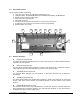
4. CONTROL INTERFACE CONNECTOR DESCRIPTION
A 25 position D-sub connector for remote control is provided on the front panel of KG506.
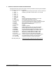
The functions of each pin are as follows;
1 CH 0, 1 apply 1 to 6 bits of binary input to pins 1 thru 6 to select 64
2 CH 1, 2 channels, pull “LOW” for active state. Pin 1 is LSB.
3 CH 2, 4
4 CH 3, 8
5 CH 4, 16
6 CH 5, 32 MSB
7 GROUND Ground
8 RSSI Receive Signal Strength Indication, 0 to 5 V DC
9 DISC. OUT Discriminator audio output, low level
10 SQ. CONT. To external Squelch control, 10K pot to ground
11 BUSY Goes to 5V logic high when squelch is opened by signal
12 MUTE When pulled low, mutes RX and Repeat audio
13 MOD-1 Microphone modulation input
14 GROUND Ground
15 PTT Pull low to transmit
16 MOD-2 Digital modulation input, TTL level, DC sensitive
17 SIMPLEX Provides logic output during simplex operation
18 ERROR Provides “flashing” high/low if error/alarm is present
19 DECODE Logic low upon decoding 5-tone or DTMF code
20 RX AUD-1 With pin 21, provides balanced “0 dBm” audio
21 RX AUD-2 With pin 20, provides balanced “0 dBm” audio
22 TX OUT Indicates error in PA, low power or high SWR
23 EXT. POW SW Connect to ground through external POWER switch
24 VOLUME To external volume control, 10 K pot to ground
25 +12V (nom) Switched 13.6 VDC to external accessories
CN1 Mini phone jack Balanced Speaker output both sides above ground
.