REGATTA™ 2 Synthesized Marine Transceiver VHF/FM 25/1 Watt Models RG2W or RG2B Page 1
4.7 4.8 TABLE OF CONTENTS 1 ABOVE ALL... SAFETY!..................................................................4 1.1 1.2 5 Symbols used..............................................................................4 Warnings.....................................................................................4 1.3 1.4 1.5 2 3 3.1 3.2 3.3 3.4 3.5 3.6 3.7 6 7 Contents of package .................................................................10 Location for the transceiver ........................
9.4 9.5 9.6 “ Log” (list of registered calls) ....................................................23 “Dir” (Entries in the directory) ....................................................23 “Posn”(Setting of position co-ordinates and adjustment of UTC time) 24 9.7 ”LCD” (display contrast) ............................................................24 9.8 “Beep” (Enable/disable keypad beep) .......................................24 9.9 “ZONE”(Adjustment of UTC time deviation) ..............................
1 ABOVE ALL... SAFETY! 1.1 Symbols used with current regulations. Not following these instructions can cause personal injury and/or malfunction of the device. , For ease and convenience of viewing, REGATTA 2 uses symbols to highlight urgent situations, practical advice, and general information. , Warnings such as this, shown using an open hand symbol, indicate a crucial description regarding technical repairs, dangerous conditions, safety warnings, advice and/or important information.
1.4 ____________________________________________ Assistance We urge you to write the serial number of your transceiver in the space provided below. This number is found on the back panel of the transceiver and will be useful in the event of repair/assistance and/or loss and/or theft. NOTE IN CASE OF EMERGENCY If you have need of assistance, contact other vessels and the Coast guard by sending a distress signal on Channel 16. USING CHANNEL 16 DISTRESS CALL PROCEDURE .
INTRODUCTION General Congratulations for choosing Midland’s REGATTA™ 2 marine transceiver. This product is a high performance, mobile VHF DSC marine transceiver. The following are its principle features: • Equipped with all international channels available (correctly assigned). • High transmission power of 25W, which allows the user to maintain contact from large distances, and a low transmission power of 1 W to reduce power consumption during short-distance communication and for in harbor use.
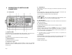
2 DESCRIPTION OF CONTROLS AND CONNECTORS 2.1. Front panel (5) FUNCTION keys They enable to enter into the menu pages, to activate some functions such as Triple Watch or SCAN. (6) H/L Push the H/L button to select high transmission power (25W) or low power (1W). The LCD display will show HI (high power) or LO (low power). The H/L function is accessible in normal VHF or MEM mode. (7) (Backlight) Hold the button down to activate the display and keypad backlight (“LITE” appears on the display).
2.2 , Back panel (connections) Warning! Faulty connections or short-circuits may seriously damage REGATTA 2. Before attempting any connections, consult the specialized sections of this manual. 1) Antenna Jack This SO 239 jack is for connecting an appropriate antenna. 2) Power cable This red/black cable has to be connected to a power source of 12 V DC (red is positive.
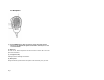
2.3. Microphone (1) UP and DOWN buttons These two buttons change the tuning channel. The first scrolls upwards through the tuned marine channels, the second scrolls downwards. (2) Button 16 For ease of use, button 16 performs the same function as button 16 on the front panel of the transceiver. (3) PTT (push to talk) Pressing this button will begin transmission. (4) Microphone During transmission, speak with the microphone a few inches away from your face.
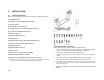
3. INSTALLATION 3.
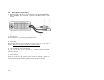
6. 3.3 Mounting the transceiver To mount the transceiver to your vessel (see following picture): 1. 2. , 3. 4. , 5. Choose an appropriate location, as explained in the paragraph above. Position the mounting bracket on the surface upon which it will be fixed, use a pencil to draw the position of the four holes where the screws will be inserted. 7.
3.5 Installation of the antenna/electromagnetic exposure For optimal radio settings and minimal user exposure to electromagnetic radio frequency energy, ensure that: • The antenna is connected to the transceiver and is properly installed. • The antenna is situated away from people and is positioned at least three feet from the transceiver and microphone. • The connector is a standard PL259 (male UHF). 3.
3.7 Connections Refer to the following diagram: Wire Colors of Accessory cable: GREEN: to GPS + YELLOW: to GPS 3.7.c Antenna The antenna is an extremely important part of the device and noticeably influences the settings of any telecommunications device. Contact your supplier regarding the antenna and request advice about how to mount and best connect it to your transceiver. , 3.7.a Power Supply The transceiver power supply must be 12V DC (see Technical Specifications, Sec.12).
4. BASIC OPERATION 4.1 Turning REGATTA 2 on/off 4.4 4.4a To turn the transceiver off, rotate the knob counter-clockwise until you hear a click: the LCD display will turn off. If your transceiver is not connected to a GPS receiver, it is necessary to manually insert your coordinates, otherwise an alarm will continue to sound. For further details, see Par.6.1 & 6.3. 4.2 Volume regulation Bring the ON/OFF/VOLUME knob first to medium volume.
The PTT (Push-To-Talk) button is located on the external microphone of your REGATTA 2. To transmit: 1. 2. Ensure that no one else is speaking. Hold down the PTT button on the microphone. TX will appear on the Display. 3. Wait a second, then speak in a normal voice about 2 inches from the microphone. 4. When you have finished, release the PTT button: TX will disappear from the display. Now REGATTA 2 is in receiving mode (silent and waiting for a signal) where it will automatically receive any communication.
• 5 SCANNING FUNCTIONS 5.1 Channel scanning REGATTA 2 can automatically search for signals throughout the marine band by scanning, or selecting the channels in rapid sequence. When a signal is detected, the scanning pauses on that channel and remains blocked until the signal ends. Before the scanning automatically starts again, REGATTA 2 waits for a few seconds in case the user wishes, if necessary, to respond to a call even if in truth you will see the channels being scanned.
inserted into scan cycle, select the channel press and hold the “M/S” function key until the display shows “M/S Del”. (Fig. I) . 4. 5.4a Similar to scanning of marine channels, Dual Watch and Triple watch stop when a signal is found and remain blocked for a few seconds after the signal disappears, in order to give the user a chance to respond to a call, if necessary. Dual/Triple Watch cannot function correctly if the squelch is not correctly regulated, as described in par .4.
6 7 DIGITAL SELECTIVE CALLING (DSC) 7.1 Introduction USE WITH GPS 6.1 Function If connected to a GPS receiver, the transceiver will display the vessel position (latitude and longitude), as well as time data. If information regarding position data are not received, in the normal radio mode, time data does not appear and a minutelong warning tone will sound (can be deactivated by pressing any button). This tone will sound every 4 hours, reminding the user that position data needs to be inserted.
7.4 Sending an individual call You can carry out an individual call using the following procedure: 5. Press briefly the function key corresponding to CALL. On the display appears: 6. The outlined line below under "Routine To” appears if no owner name was inserted in the column “Dir”, otherwise a similar situation may appear: In this case the answer is reached from ship 100000000 and the possible communication channel will be CH06.
7. 8. 9. Like mentioned above, it is possible, to insert manually the address of who is desired to call (using the alphanumerical keypad), or to select one of the addresses previously stored (maximum 16) by pressing several times the function key related to “DIR”. Then, after you have selected the communication channel and the owner address, the call can be carried out by pressing the function key corresponding to the script “Send” and confirmed by pressing the “E” button.
H. I. L. M. GROUNDING LISTING SINKING ADRIFT 4. To send out the distress call hold down the DISTRESS-button for 5 seconds. An acoustic alert will emit and the distress call will be carried out on channel 70 even when the channel is in use. After the distress call, the transceiver will simultaneously check channel 70 and channel 16 on a receipt of DSC confirmation and meanwhile appears following: 5. 6.
8 8.2 Receiving a DSC call When the user receives a DSC call, the transceiver will automatically respond according to the type of call. Information shown on the LCD display will vary according to the type of call. Refer to the diagram below for several examples: DISTRESS CALL GENERAL CALL TO ALL VESSELS General call to all ships When the transceiver receives a general call related to all vessels, it automatically moves to the communication channel and emits an acoustic emergency alarm.
9 CUSTOMIZATION 9.1 Menu settings 9.5 REGATTA 2 can carry out a series of settings in order to personalize the transceiver to your requirements and to insert the necessary data to its operation. 9.2 1. 2. 3. 4. Navigation in the menu of settings To access the menu of setting use the functions keys. All programmed settings are stored in non-volatile memory. 9.3 List of settings Following find the possible settings: Menu Items Log Dir Posn LCD Beep ZONE MMSI 9.
4 If you desire to change the name or the code, press one of the 2 function keys associated to the name or the MMSI code “►”. 9.7 “LCD” (display contrast) The user can adjust the display contract to optimise visibility according to ambient conditions. 1. Press the function key “DSC”. Fig. W 2. Press the function key “Menu”. 3. Press the function key “LCD”. 4. Using the function keys corresponding to “▼” ; “▲” you can increase the contrast of the display. 9.b.
9.9 “ZONE” (Adjustment of UTC time deviation) The user can program the time deviation with respect to the UTC time so the transceiver’s display will show the time for the current time zone. 5. 1. 2. 3. 4. 5. 6. Press the function key “DSC”. Press the function key “Menu”. Press the function key “More”. Press the function key “ More”. Press the function key “Zone”. The display will show 6. 7. 8. Pressing the function keys “+” or “–“ will set the desired deviation.
11 Troubleshooting Problem Possible causes Power supply is not correctly connected Device doesn’t turn The protection fuse has shorted on (located on the power cable) Solution Refer. Verify that power supply is 3.7.a properly connected Verify the cause of the problem and substitute the fuse Antenna is not correctly connected Verify that antenna is 3.7.c Device turns on, but properly connected doesn’t receive Volume level is too low Adjust volume level 4.
12 TECHNICAL SPECIFICATIONS: Channels .................................................. All 48USA, 55 Canadian & 57 international marine channels, Frequency generation ......................................................................................................PLL synthesizer Frequency range ..................................................................................TX from 156.025 to 157.425 MHz ...............................................................................................
13 Frequency Table Channel Number INT CAN US 01 01 02 03 04 02 03 04A 05 06 07 08 09 10 11 12 13 14 15 16 17 18 05A 06 07A 08 09 10 11 12 13 14 15 16 17 18A 19 20 19A 20* 21 21A 21B Page 28 Frequency MHz TX 156.050 01A 156.050 156.100 156.150 156.200 156.200 156.250 05A 156.250 06 156.300 156.350 07A 156.350 08 156.400 09 156.450 10 156.500 11 156.550 12 156.600 13 156.650 14 156.700 156.750 15 16 156.800 17 156.850 156.900 18A 156.900 156.950 19A 156.950 20 157.000 20A 157.000 157.050 21A 157.
INT CAN US 78 79 80 81 82 83 84 TX RX Mode 156.925 78A 78A 156.925 156.975 79A 79A 156.975 157.025 80A 80A 157.025 157.075 81A 81A 157.075 157.125 82A 82A 157.125 83 157.175 83A 83A 157.175 84 84 157.225 161.525 156.925 161.575 156.975 161.625 157.025 161.675 157.075 161.725 157.125 161.775 157.175 161.825 D S D S D S D S D S D S D 85 85 85 157.275 161.875 D 86 86 86 157.325 161.925 D 87 157.375 157.375 157.425 88A 157.425 161.975 157.375 162.025 157.
Printed in Thailand Page 30 P/N: RG500220