
User Manual

Classic owner’s manual Rev H 2056
23 | P a g e 1 0 - 0 0 1 - 1 R E V : H
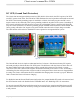
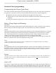
Disabling GFP
The GFP feature should only be disabled to operate the Classic in an ungrounded power system or in
systems where GFP is not required.
Press Main Menu
Scroll to the right or left until TWEAKS is highlighted and press ENTER
In TWEAKS press the right soft key to get to the MORE menu
In MORE scroll until GFP is highlighted
Use the up and down arrow keys to toggle between on and off
Press ENTER to save
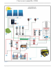
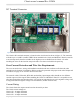
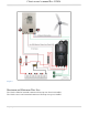
Wiring the Classic
WARNING: Shock hazard. Disconnect the batteries and input power before opening the
Classic front cover. ALWAYS use proper Over current and disconnects on the PV+ and Battery + at the
Classic.
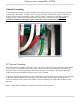
When two or more Classics are paralleled onto one SINGLE DC Source, a blocking diode must be used
between each Classic and the input source to isolate each Classic from the other ones. With Solar arrays
you would have one array per Classic, this only applies to larger wind or hydro turbines.
The Classic should be wired by a qualified professional and needs to meet all applicable electrical codes.
Always make sure all source and battery circuits are de-energized and wait 5 minutes before working on
the wiring in the Classic. The Classic has 2 common neutral (negative) terminals. Therefore, only one
neutral conductor is required to run from the E-Panel and terminate on either (or both) common neutral
terminal. This negative conductor should be sized to match the battery + cable. The Positive DC source
wire goes to the PV+ Turbine+ screw. The Positive Battery DC wire goes to battery + terminal. Torque the
terminal screws to the specs below.
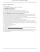
To connect the wiring to the Classic:
Ensure the DC source and Battery are disconnected
Connect a grounding conductor between the Classic and system ground
Ensure the breaker between the battery and Classic meets UL489 standards.
Ensure the breaker between the DC source and Classic meets UL1077 standards.
Connect the DC source and Battery wire to the Classic
Connect any communications cables or auxiliary input/output wires
Torque terminal connector screws to the following specs
The Torque specs on the DC terminal connector (big blue terminal connector) are:
Up to #10 AWG torque to 25-35 inch pounds.
#8 AWG torque to 30-40 inch pounds.
#6 AWG or above. Torque to 40-50 inch pounds.