
User Manual

Classic owner’s manual Rev H 2056
42 | P a g e 1 0 - 0 0 1 - 1 R E V : H
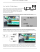
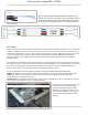
operate at either normally open, (Active High) or normally closed (Active Low) when the Aux 1 function
condition is true. For more information see Configuring Auxiliary Input/Output on page 36.
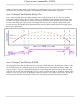
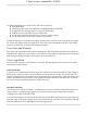
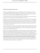
Aux 1 Voltage-Time Relation (Relay/12v)
Aux 1 Function Graph shows the relationship between voltage and time of AUX 1. (The axis labeled
VOLTAGE could be battery, PV, wind input voltage, etc. depending on the function selected by the user)
VHIGH is the upper voltage limit, as soon as the voltage reaches this limit the Delay time will then start;
as soon as the Delay time expires AUX1 will change state and stay there until the voltage drops below
VLOW set point, then another timer called Hold Time will start and when this expires the output will go
back to the original state.
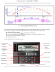
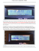
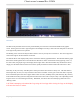
Aux 2 Voltage-Time Relation (PWM)
The graph below describes the relation in Aux 2, between voltage and time. The difference in Aux 2 is the
use of PWM running at a hundreds of Hz rate and is suitable for use with Solid State Relays (SSRs). The
way this works is: user sets a desired threshold and a width voltage; this means that at the desired voltage
(VOLTS), the aux will start to PWM and it has to go above or below the width to completely change states
(from 0v to 12v, or from 12v to 0v depending on the user selection, active high or active low). This gives a
much smoother transition. For more information see; Configuring Auxiliary Input/Output, page 36.
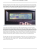
Diagram 4