MN3024DIY User Manual Hybrid Inverter / Charger User Manual MN3024DIY 10-527-1 MN3024DIY REV A 1 of 39
MN3024DIY User Manual Important safety instructions Please keep this manual for future use. The MNS Hybrid Inverter System is an all-in-one solution for 120 volt AC production, battery charging from the AC input and a built-in MPPT PV Charge Controller This manual contains all safety, installation and operating instructions for the MNS Hybrid Inverter. Please read all instructions and precautions in the manual carefully before installation and use. ØHigh voltages exist inside the MNS Hybrid Inverter.
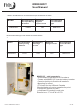
MN3024DIY User Manual CONTENTS 1. GENERAL INFORMATI ON................................ ............................................................................. 4 1.1 PRODUCT OVERVIEW AND FEATURES................................................................................................... 4 1.2 BASIC SYSTEM INTRODUCTION........................................................................................................... 5 1.3 APPEARANCE.........................................................
MN3024DIY User Manual 1. General information 1.1 Product overview and features - DIY series is a new all-in-one hybrid solar charger/ inverter, which integrates battery MPPT solar & AC input charging with sine wave output. Thanks to DSP control and advanced control algorithm, it has fast response speed, high reliability and high industrial standards. Four charging modes are available, i.e. Only Solar, Mains Priority, Solar Priority and Mains & Solar hybrid charging; and two output modes are available, i.e.
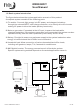
MN3024DIY User Manual 1.2 Basic system introduction The figure below shows the system application scenario of this product. A complete system consists of the following parts: 1. PV module: Converts light energy into DC power, and charges the battery through the onboard MPPT solar charge controller, or to directly drive the inverter making AC power to drive the loads. (battery-less mode) 2. Mains or generator: Connected at the AC input, to power the loads while charging the battery.
MN3024DIY User Manual 1.
MN3024DIY User Manual 2. Installation Instructions 2.1Installation precautions Be very careful when installing the battery. Wear safety glasses when installing a lead-acid flooded battery. If you come into contact with the battery acid, rinse with clean water immediately. Do not place metal objects near the battery to prevent short-circuit of the battery terminals. Hydrogen gas may be generated when the battery is charging. Please ensure good ventilation.
MN3024DIY User Manual 2.2 Wiring specifications and circuit breaker selection Wiring and installation must comply with national and local electrical codes.
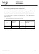
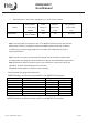
MN3024DIY User Manual ➣ Refer to the table below for recommended AC input wire diameter and switch: Recommended AC Input Wiring Diameter Model MN3024DIY Maximum bypass input current 8 AWG 40A Recommended circuit breaker type MNEAC40 Recommended battery input wire diameter and switch selection ➣ Model Recommended battery wiring diameter MN3024DIY 2 AWG Rated battery discharge current 125A Maximum charge current 100A Recommended circuit breaker type MNEDC125 MNDC125 sold separately ·A conve
MN3024DIY User Manual ➣ Recommended AC output wiring specifications and circuit breaker selection Models MN3024DIY Recommended Rated Maximum AC output wiring inverter AC bypass output Recommended diameter output current type 8mm 2/ 8AWG 25A 40A 2P—63A circuit breaker Note: The wire gauge is for reference only.
MN3024DIY User Manual 2.1Installation and wiring : Installation steps: Step 1: Determine the installation position and the space for heat dissipation. Determine the installation position of the MNS Hybrid Inverter, such as wall surface; when installing the MNS Hybrid Inverter, ensure that there is enough air flowing through the heat sink, and space of at least 200mm/8 inches to the left and right air outlets of the inverter are open to ensure natural convection heat dissipation.
MN3024DIY User Manual Step 2: Remove the terminal cover Step 3: Wiring AC input / output wiring method: ① Prior to AC input/output wiring, disconnect the external circuit breaker and confirm that the wire used is the appropriate AWG. Please refer to Section 2.2 on pg. 8 “Wiring Specifications and Circuit Breaker Selection”; ② Properly connect the AC input wire according to the wire sequence and terminal position shown in the igure on the next page.
MN3024DIY User Manual :Ground L:Live N :Neutral ③ Properly connect the AC output wire according to the wire sequence and terminal position shown in the figure below. Please connect the ground wire first, and then the hot wire and the neutral wire. The ground wire is connected to the grounding screw hole on the cabinet using a ring terminal or copper lug. :Ground L:Live N :Neutral Note: The grounding wire shall be as large as possible (Not less than 10 AWG).
MN3024DIY User Manual PV input wiring method: ① Prior to wiring, disconnect the external circuit breaker and confirm that the wire used is appropriate AWG. Please refer to Section 2.2 “Wiring Specifications and Circuit Breaker Selection”; ② Properly connect the PV input wire according to the wire sequence and terminal posi on shown in the figure below.
MN3024DIY User Manual BAT +: Battery positive electrode BAT - : Battery negative electrode Warnings: ① Mains input, AC output and PV array are all high voltage. So, before wiring, be sure to disconnect the appropriate circuit breaker. ② Be very careful during DC wiring; do not close the circuit breaker during wiring, and ensure that the “+” and “-” pole leads of each component are connected properly; a circuit breaker must be installed at the battery input terminals. Refer to Section 2.2 on pg.
MN3024DIY User Manual Step 5: Install the terminals cover. Step 6: Turn on the MNS Hybrid Inverter First, close the circuit breaker at the battery terminal, and then turn the rocker switch on the left side of the machine to the "ON" position. The "AC/INV" indicator flashing indicates that the inverter is working normally. Close the circuit breakers of the PV array and the AC Mains. Finally, turn on AC loads one by one to avoid overcurrent caused by a large momentary load from turning on loads all at once.
MN3024DIY User Manual 3. Operating modes 3.1 Charging mode 1) PV priority: PV module will charge the battery preferentially, and the battery is charged by the Mains only when the PV system fails. During the day, solar energy is fully used to charge, while at night, it renverts to the Mains. This can maintain battery level, and is ideal for areas where the grid is relatively stable and electricity price is relatively high. 2) Mains priority: The Mains supply is preferentially used to charge the battery.
MN3024DIY User Manual 3.2 Output mode ➣ PV priority mode: Loads are powered by the PV module and battery. Diversified charging mode and output mode are optional. When PV priority mode is selected, utilization of green solar energy can be maximized to achieve energy saving and emission reduction. Switch to mains supply when the PV charging is not available. This mode maximizes the use of solar energy while maintaining battery power, suitable for use in the areas with relatively stable grid.
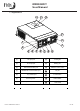
MN3024DIY User Manual 4. LCD screen operating instructions 4.1 Operation and display panel The operation and display panel is as shown below, including 1 LCD screen, 3 indicators and 4 operation buttons.
MN3024DIY User Manual LCD screen introduction Icons Functions Indicates that the AC input terminal has been connected to the grid Icons Functions Indicates that the inverter circuit is working Indicates that the AC input mode Indicates that the machine is in in APL mode (wide voltage range) the Mains Bypass mode Indicates that the PV input terminal has been connected to the solar panel Indicates that the AC output is in an overload state Indicates that the machine has Indicates the percentage of
MN3024DIY User Manual Indicates that the current battery Indicates that the unit has an type of the unit is a lead acid - alarm battery Indicates that the battery is in Indicates that the unit is in a charging state fault condition Indicates that the AC/PV charging Indicates that the unit is in circuit is working setup mode The parameters displayed in the middle of the screen: 1. In the non -setup mode, the Indicates that the AC output alarm or fault code is displayed.
MN3024DIY User Manual Real -time data viewing method On the LCD main screen, press the of the machine.
MN3024DIY User Manual Parameter Parameter no. name 00 Exit setting menu Settings Description [00] ESC Exit the setup menu PV priority mode , switching to the Mains when [01] SOL the PV fails or the battery is lower than the set value of parameter [04]. 01 Output source priority [01] UTI default Mains priority mode, switching to inverter only when the mains fail .
MN3024DIY User Manual Parameter Parameter no. name Settings [06] CSO [06] CUB Description PV priority charging ; when not PV is unavailable, charging from the mains is started. M ains priority charging; When charging from the mains is not available PV charging is started. PV and Mains hybrid charging; PV charging is a priority, and when the PV energy is insufficient, Charger 06 the Mains charging supplements. When the PV source priority energy is sufficient, the Mains charging stops.
MN3024DIY User Manual Parameter Parameter no. name Settings [08] NCA Battery boost 09 charge voltage [09] 28.8V default Description Ternary lithium battery; Default absorption voltage is 28.4V adjustable. Boost (absorb) charge voltage setting; the setting range is 24~29.2V with a step of 0.2V for user- defined battery and lithium battery.
MN3024DIY User Manual Parameter Parameter no. name Settings Description Battery discharge limit voltage; when the Battery 15 discharge battery voltage is lower than the point, the [15] 20V default limit voltage output is turned off immediately ; t he setting range is 20V~ 26V, with a step of 0.2V. It is valid for user - defined battery and lithium battery.
MN3024DIY User Manual Parameter Parameter no. name Settings Description Automatic restart when overload is enabled. If an overload occurs and the output is turned off, [23] ENA default the unit will restart after a delay of 3 minutes . After it reaches 5 cumulative times, the unit will not restart.
MN3024DIY User Manual 4.3 Battery type parameters For Lead - acid Battery : Battery type Sealed lead acid battery (SLD) Colloidal lead Vented lead acid battery acid battery User - defined (User) (GEL) (FLD) 30V 30V 31V 18~30V 29.2V - 29.6V 18~30V 28.8V 28.4V 29.2V Parameters Overvoltage disconnection voltage Equalizing charge voltage Absorption charge Float charge voltage Undervoltage alarm voltage 27.6V 27.6V 27.6V 22V 22V 22V voltage 21.2V 21.2V 21.
MN3024DIY User Manual For Lithium Battery : Battery type Parameters Lithium iron phosphate battery Lithium iron phosphate battery Lithium iron phosphate battery - Ternary lithium battery Ternary lithium battery (N 06 ) (N 07 ) (LF0 7) (LF0 8) (LF09) (User) 30V 30V 30V 30V 33V 18~30V User defined Overvoltage disconnection voltage Equalizing charge voltage Absorbtion charge voltage Float charge voltage 24.6V 28.7V 24.6V 28.4V 31.
MN3024DIY User Manual 5. Other functions 5.1 Dry contact Working principle: This dry contact can start and stop the generator to charge the battery.① Normally, the terminals are that the NC-N point is closed and the NO - N point is open; ② When the battery voltage reaches the low voltage disconnection point, the relay coil is energized, and the terminals turn to that the NO - N point is closed while NC - N point is open.
MN3024DIY User Manual 6. Protection 6.1 Protections provided No. 1 Protections PV current /power When charging current or power of the PV array configured exceeds limiting protection the PV rating, it will charge at the rated value. PV night reverse 2 3 At night, current is prevented from flowing back into the panels.
MN3024DIY User Manual PV reverse polarity 10 protection AC reverse 11 protection Battery input over 13 current protection Battery input 14 protection Charge short 15 Prevents the inverter output from backfeeding into the AC input. protection Bypass over current 12 When the PV polarity is reversed, the unit will not be damaged. protection 10-527-1 MN3024DIY REV A Built -in AC input overcurrent protection circuit breaker.
MN3024DIY User Manual 6.
MN3024DIY User Manual 6.3 Troubleshooting Faults Handling measures Check if the battery circuit breaker or the PV circuit breaker are closed; No display on the screen if the switch is in the "ON" state; press any button on the screen to exit the screen sleep mode. Battery overvoltage Measure if the battery voltage exceeds rating, and turn off the PV protection array and Mains circuit breakers.
MN3024DIY User Manual 7. System maintenance ➣ In order to maintain the best long - term performance, it is recommended to conduct the following checks twice a year. 1. Make sure that the airflow around the unit is not blocked and remove any dirt or debris from the heat sink. 2. Check that all exposed wires are not damaged by exposure to sunlight, friction with other objects around them, dryness, damage by insects or rodents, etc., repair or replace if necessary. 3.
MN3024DIY User Manual 8. Technical parameters Model MN3024DIY AC mode Rated input voltage Input voltage range 110/ 120Vac (90Vac- 140Vac) ± 2% Frequency 50Hz/ 60Hz (Auto detection) Frequency 47±0.3Hz ~ 55±0.3Hz (50Hz); 57±0.3Hz ~ 65±0.
MN3024DIY User Manual Maximum Efficiency Overload protection >92 % (102% < load <1 10%) ± 10%: report error and turn off the output after 5 minutes; (110% < load < 1 25%) ± 10%: report error and turn off the output after 10 seconds; Load >125 % ± 10%: report error and turn off the output after 5 seconds; Peak power 3000VA Loaded motor 1HP capability Rated battery 24V (Minimum starting voltage input voltage 22V) Battery Undervoltage alarm/shutdown voltage/overvoltage alarm /overvoltage recovery...
MN3024DIY User Manual Battery 20 –33Vdc voltage range Maximum 1400W output power PV charg ing current range 0-60A (can be set) Charging short circuit fuse protection Wiring Reverse polarity protection protection Hybrid charging Max charger current specificatio ns (AC charger+PV charger) Max charger current (settable) 0-100A Certified specifications Certification CE(EN62109- 1) EMC certification EN61000 , C2 level Operating temperature - 15°C to 55 °C range Storage temperature - 25°C ~ 60 °C
MN3024DIY User Manual MIDNITE SOLAR INC. LIMITED WARRANTY MidNite Solar DIY inverters, DIY sheet metal enclosures, DIY breaker boxes and DIY accessories MidNite Solar Inc. warrants to the original customer that its products shall be free from defects in materials and workmanship. This warranty will be valid for a period of ONE (1) year for all DIY series inverters, DIY sheet metal enclosures, DIY breaker boxes and DIY accessories.