
Installation manual and specs


MNDC Installation Instructions
Rev: New Page 4 of 7
Battery Negative connection
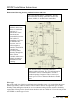
The wiring diagram shows a 500 amp shunt. This is used to measure voltage drop across the
shunt to aid in calculating battery state of charge. The shunt does not ground the battery negative
circuit. If this shunt is not installed, then you may use the 5/16” stud directly above the shunt
area as a battery negative tie point. Using this tie point will ground the battery negative to the
chassis. Grounding the battery negative is not allowed when employing a DC-GFP device. The
inverter side of the shunt or the 5/16” stud are also an ideal tie point for PV negative or other DC
negative circuits.
Battery status monitor systems such as the Trimetric, E-Meter, Trace Meter etc are available with
or without the 500 amp 50mV shunt. The MNDC does not come with this shunt, so you will
need to order the shunt.
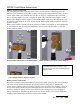
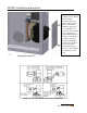
Shunt mounted horizontal on bottom dimples Shunt mounted vertical on bottom dimples
5/16” stud for battery negative tie point
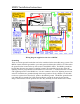
Battery Positive connections
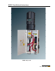
DC positive from the battery bank connects to the lower section of the large DC inverter breaker.
The lower inverter breaker stud is also the common point for connection of additional DC
circuits such as from the output of a charge controller. Do not connect other charging sources to
the top of the inverter breaker as this would apply power to the inverter even when the inverter
breaker is turned off. The top section of the inverter breaker connects to the inverter positive
battery terminal post. The following photo shows the inverter breaker wired with an additional
charging source connected to the bottom section of the breaker.
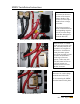
The hardware kit bag contains a 5/16”
kepnut for use with this grounding battery
negative stud.