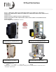
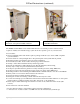
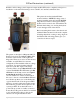
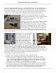
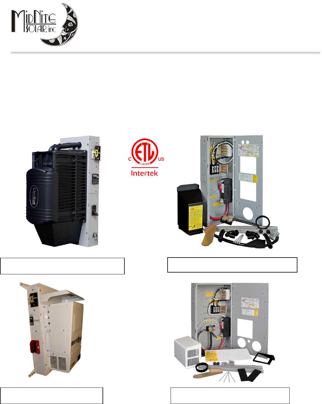
E-Panel Instructions Model: MNE125ST, MNE175ST, MNE250ST, MNE125AL, MNE175AL, MNE250AL, MNE175STS, MNE250STS, MNE125LT, MNE175LT, MNE250LT, MNE125ALT, MNE175ALT, MNE250ALT, MNE125AL PLUS, MNE175AL PLUS, MNE250 PLUS MNE125STM, MNE175STM, MNE250STM, MNE125ALM, MNE175ALM, MNE250ALM, MNE125STMM Left and Right hand 120/240VAC versions OutBack E-Panel as installed (narrow) Left Hand Magnum as installed Regular (narrow) OutBack E-Panel parts Right Hand Magnum E-Panel parts Model Number code: MNE-------------
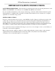
E-Panel Instructions (continued) IMPORTANT SAFETY INSTRUCTIONS SAVE THESE INSTRUCTIONS - These instructions contain important safety and operating instructions for the MidNite Solar MNPVHV solar combiner boxes and MNDC156-600 Disconnect Switch. If you do not fully understand any of the concepts, terminology, or hazards outlined in these instructions, please refer installation to a qualified dealer, electrician or installer.
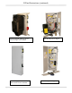
E-Panel Instructions (continued) Stretched OB with OB surge arrestor Gray steel right or left available E-Panel LT, gray steel version White aluminum also available 3|Page Stretched OB parts as shipped E-Panel LT parts as shipped 10 -003-1 REV: G
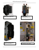
E-Panel Instructions (continued) E-PANEL PLUS AS INSTALLED White aluminum left hand only E-PANEL FOR MAGNUM MM SERIES AS INSTALLED 4|Page E-PANEL WIRED With MNSPD Surge Protector Devices & charge control breakers MM SERIES E-PANEL WIRED 10 -003-1 REV: G
E-Panel Instructions (continued) Magnum-AE version 120/240VAC These models have their own separate installation manual This shows the parts that come with the 120/240VAC E-Panels The MidNite Solar E-Panel comes standard with the basic over-current protection and disconnects required to install your renewable energy system. It can also expand to grow as your needs arise.
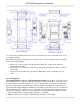
E-Panel Instructions (continued) Note: The Stretched OutBack E-Panel uses the 14.41” Magnum chassis. The LT and MM version use the 9.41” OB sized chassis. The dimensioned chassis drawings above show the location of the conduit knockouts, mounting holes and mounting brackets. Knockouts on the top surface are directly in line with ones on the bottom surface for stacking units vertically. Knockouts on the lower end of each side are directly in line with each other for stacking horizontally.
E-Panel Instructions (continued) 3. OutBack MF80 should be left hand hinge (No knock out on the right side of chassis) 4. MX60 works equally as well on either side 5. WX controller works equally as well on either side 6 C40/C60 and Tri-star work equally as well on either side 7. Blue Sky has the heatsink on the left, so should use a right hand hinge. See E-Panels explained on the MidNite website www.midnitesolar.com for exact part numbers of door options and an explanation of each E-Panel platform.
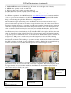
E-Panel Instructions (continued) You can make life a little easier by installing additional breakers for charge control, the inverter and such while the E-Panel is still lying horizontal on a table. Do as much of the additional wiring as possible before hanging the E-Panel on the wall. The following pictures show some of the operations that can be done “on the bench” where access is optimal. Be careful not to dislodge larger knockouts on concentric knockouts Break off circuit breaker tabs.
E-Panel Instructions (continued) Breakers such as charge control input and output and DC-GFP can be completely wired prior to installation on the wall. Field wiring is done at the PV, AC and DC terminal bus bars. This picture shows the Outback E-Panel mounted with two MNEPV63 charge control breakers installed and an AC and DC MNSPD Surge Protector Device. The upper mounting bracket can be secured to the wall and then the E-Panel chassis hung onto it using the keyhole slots in the upper back of the chassis.
E-Panel Instructions (continued) employ a sub panel circuit breaker box, you can make this neutral to ground bond in the subpanel. It is technically better to make this bond closest to the source of power (the E-Panel), but many electrical inspectors will be looking for it in the sub-panel box. It will work just fine in either location, just make sure you have adequate conductor sizes between the E-Panel and the sub-panel. Do not rely on the hinges for grounding the equipment mounted to the door.
E-Panel Instructions (continued) 4. The + (line) marking on the breaker would seem to indicate that you should connect the PV+ to this terminal since the PV+ is the highest potential in the system. Our testing shows this would be correct. The + side of the breaker needs to be connected to the highest potential per the breaker instructions. 5. The - side of the PV in breaker goes to the charge controller PV+ input terminal. 6.
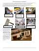
E-Panel Instructions (continued) Mounting the inverter The 6 x 20mm pan head Philips screws for mounting the inverter are taptite (thread forming). Use one of these 6mm screws to pre-tap threads into the steel doors extruded funnel holes. Aluminum doors have press nuts and do not require tapping. Make sure to install all ¼” star washers to bite through the powder coating. One of the best features of the MidNite E-Panel is that one person can do all the lifting.
E-Panel Instructions (continued) Doors installed, plastic conduit installed, wiring complete. Note the battery cable routing. It is important to route cables so the doors close freely without undue force. The left E-Panel battery cables came from above, but could have come from below or back. More tidbits to digest Important! Torque din rail mount breakers to 20 in lb. Wait one hour and re-torque. Installing the breaker cover Six locations are available for additional 13mm wide breakers.
E-Panel Instructions (continued) You may be surprised that what you thought was a tight connection actually pulls out with little effort. This is caused be a phenomenon called cold flow. Copper is a relatively soft metal and will continue to move under inadequate clamping pressure. A 20 inch pound of torque takes a lot of strength! Use the supplied UL listed plastic 2” x 6” spacers to separate AC and DC breakers if installed on the same din rail. Barriers are required per NEC between AC and DC circuits.
E-Panel Instructions (continued) This basic wiring diagram is mounted on the inside of the hinged door. Elsewhere in these instructions is a slightly expanded version of the E-Panel wiring diagram. There is an AutoCAD version of the expanded wiring diagram at www.midnitesolar.com This is provided so that interested parties may download and modify it to tailor their specific system configuration. When stacking two OutBack inverters, it may be required to add the OutBack PSX-240 autotransformer.
E-Panel Instructions (continued) E-Panel parts locator, Door Supplied insulators to achieve required separation of AC and DC circuits E-Panel parts locator, internal 16 | P a g e Ground to Neutral connection 10 -003-1 REV: G
E-Panel Instructions (continued) 17 | P a g e 10 -003-1 REV: G
E-Panel Instructions (continued) Magnum MS4448-AE & MS4024-AE system pre-wire with DC-GFP MNSPD MNSPD MNSPD AC AC DC BATTERY CABLES MUST BE FINE STRAND SUPER FLEXIBLE SUCH AS COBRA CABLE OR EQUIV. COBRA CABLE IS THW LISTED. 2/0 CABLE SHOULD HAVE 1330 STRANDS, 2AWG SHOULD HAVE 665. AC WIRING MUST BE APPROVED FOR RESIDENTIAL WIRING PER THE NATIONAL ELECTRIC CODE, SUCH AS THHN AS AN EXAMPLE 30 AMP DUAL 50 AMP DUAL 50 AMP DUAL MTG BRKT TOP AND BOTTOM DIN RAIL MOUNT BREAKERS 20 IN-LBS (2.