
Instruction Manual

E-Panel Instructions (continued)
10 | P a g e 1 0 - 0 0 3 - 1 R E V : G
employ a sub panel circuit breaker box, you can make this neutral to ground bond in the sub-
panel. It is technically better to make this bond closest to the source of power (the E-Panel), but
many electrical inspectors will be looking for it in the sub-panel box. It will work just fine in
either location, just make sure you have adequate conductor sizes between the E-Panel and the
sub-panel. Do not rely on the hinges for grounding the equipment mounted to the door.
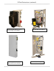
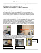
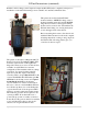
The picture to the left shows the charge control bracket
supplied in the E-Panel kit. This one is for a left hand hinged
unit, so the charge control bracket is on the right side
opposite the din rail breakers.
The charge control bracket supplied works with the OutBack
MX60, MF80, MidNite Classic and Xantrex WX charge
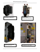
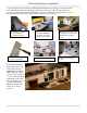
controllers. The Charge control bracket is secured to the E-Panel
with 3 #10 x 3/8” sheet metal screws. Use one more screw to
secure the top bracket of charge controller and a 1” close nipple on
the side as shown below. Note that it takes three 1” locknuts to
mount the controller. One lock nut is used in between the E-Panel side and the charge controller side to
act as a spacer. It may help to replace the pan head screws on the side plate with flat head screws in some
cases to increase clearance.
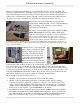
In addition to the 1” close nipple and
three locknuts, you will need plastic
threaded adapters installed on the
ends of the metal threaded nipple.
These adapters protect wires from
coming into contact with the sharp
edges of the metal close nipple.
Before wiring the charge controller,
determine what size wire and breakers
will be required. The breakers are there to protect the wiring, not the controller!
It is very common to use the MidNite 63 amp din rail breakers for this task. Even if the charge
controller is only 30 amps, it can be wired using 63 amp breakers. You will need 6AWG wire to
go with those breakers though. If using one of the more powerful 80 amp charge controllers, you
will need the MNEDC80 panel mount breakers. These mount on the opposite wall from the din
rail breakers. 4AWG wire is required to match up with these 80 amp breakers.
The flow path for the PV circuit is as follows:
1. The PV + wire comes into the E-Panel and attaches to the PV+ busbar
2. The PV- comes into the E-Panel and attaches to the shunt busbar. This is for charge
controllers that have a common PV- and battery- connection, (most are this way). Some
charge controllers like the Xantrex XW and the Blue Sky must keep thes PV- and battery-
circuits separated. The E-Panels have mounting embosses to accommodate a short white
busbar to act as an isolated PV-. Use the MNSBBW for the busbar.
3. From the PV+ busbar, use the appropriate gauge red wire (THHN) and connect to the PV+
IN breaker. DC breakers have polarity markings. These may be a + sign or a line and load
sign. Although the PV circuit has very limited energy available and thus making polarity
issues not too critical, it is best to try to get it right. This is where the fun begins.