
Instruction Manual
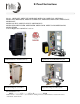

E-Panel Instructions (continued)
9 | P a g e 1 0 - 0 0 3 - 1 R E V : G
Breakers such as charge control input and output and DC-GFP can be completely wired prior to
installation on the wall. Field wiring is done at the PV, AC and DC terminal bus bars.
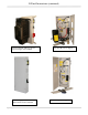
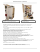
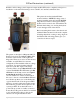
This picture shows the Outback E-Panel
mounted with two MNEPV63 charge control
breakers installed and an AC and DC MNSPD
Surge Protector Device. The upper mounting
bracket can be secured to the wall and then the
E-Panel chassis hung onto it using the keyhole
slots in the upper back of the chassis.
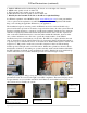
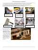
Before mounting the inverter to the chassis and
with the E-Panel mounted on the wall, complete
all wiring that will be coming to and going from
the E-Panel. The following pictures give you
some idea of what to expect.
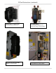
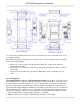
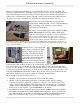
The picture to the right is a Magnum 240V E-
Panel. Notice it has an OutBack OBDC-GFP
mounted on the left side of this right hand
hinge unit. There are a total of six din rail slots
available on each E-Panel for customer
configuration. This installation has two charge
controllers. You need a breaker in the PV
input and on the DC output of the charge
controller. This took up 4 din rail slots for this
system. The MidNite DC-GFP takes up 2 din
rail slots for the 63 amp version and 2 panel
mount knock out slots for the 80 amp
version. Neither one of these would work in
this case, so the two circuit OutBack GFP was
used. It takes up three slots on the blank plate
opposite the din rails. Note the green 6AWG
neutral to ground bonding wire in this picture.
The neutral to ground bond is required on all
systems per NEC. Note that if this were a
power back up system on a utility connected
home, this bonding wire would not be installed
as it would already be there on the service
entrance. On off-grid installations that