
E-Panel Manual


E-Panel Instructions (continued)
12 | P a g e 1 0 - 0 0 3 - 1 R E V : J
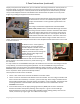
4. The + (line) marking on the breaker would seem to indicate that you should connect the PV+ to
this terminal since the PV+ is the highest potential in the system. Our testing shows this would be
correct. The + side of the breaker needs to be connected to the highest potential per the breaker
instructions.
5. The - side of the PV in breaker goes to the charge controller PV+ input terminal.
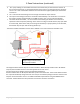
6. The output of the charge controller is sometimes marked battery+ This terminal is to connect to
the charge controller output breaker. It will not connect to the + or Line side of the breaker.
7. The other side of the breaker, + or line connects to the battery plus busbar. This connection is
important to observe polarity markings. In the event of a charge controller failure, they quite often
short internally, which means they are shorting out the battery. If proper polarity is not observed,
the breaker may not open and the wiring will burn up.
The factory installed red battery plus bus wire is 4AWG, so it is large enough for all breaker sizes.
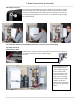
The diagrams above show 63 amp din rail mount breakers. When 80 amp breakers and or DC-GFPare
required, those breakers mount on the wall opposite the din rails. There
are three panel mount breaker slots to accommodate the 80 amp
breakers and DC-GFP. The 80 amp DC-GFP takes up two of the three slots. The third slot will be used for
the output of the 80 amp charge controller. The PV input to an 80 amp charge controller could use a 63
amp din rail mount breaker. There is no additional DC-GFP required when using the MidNite Classic
controller. The DC-GFP and arc fault protector are built into the Classic controllers.
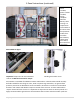
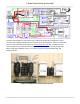
Single charge controller wiring
with 63 amp breakers