XW E-Panel Instructions Model MNE250XW The MidNite Solar XW E-Panel is designed for a single XW inverter installation. Use this installation manual to aid in installation. The installation of an electrical system such as this fall under the guidelines of the NEC in the USA. Canadian electrical codes have jurisdiction in Canada. These instructions are not intended to be used in lieu of these local and federal codes, but rather are used as specific to this product.
XW E-Panel installation manual IMPORTANT SAFETY INSTRUCTIONS SAVE THESE INSTRUCTIONS - These instructions contain important safety and operating instructions for MidNite Solar E-Panels. If you do not fully understand any of the concepts, terminology, or hazards outlined in these instructions, please refer installation to a qualified dealer, electrician or installer. These instructions are not meant to be a complete explanation of a renewable energy system.
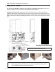
XW E-Panel installation manual Mounting The XW E-Panel: The XW inverter should be mounted to the wall prior to installing the E-Panel. Pay attention to the total height of the system. Refer to the dimensioned drawing below. Installing the E-Panel to the inverter: To install the E-Panel, remove the door and deadfront. Attach top and bottom wall mounting brackets to the E-Panel using four M6 x 10mm taptite screws supplied.
XW E-Panel installation manual Main component placement 4|Page 10-185-1 REV: -
XW E-Panel installation manual Installing the E-Panel to the inverter continued: Remove two 5mm #2 Philips tip screws from the bottom of the inverter that will be used to attach the E-Panel. These two screws are the only attachment to the inverter. The bottom wall mounting bracket also needs to be secured to the wall. You must also remove the battery terminal bolts prior to setting the E-Panel in place. Note: 10-32 UNF screws are interchangeable with the 5mm screws if you should misplace them.
XW E-Panel installation manual Wiring: Start with the grounds. Wiring the system will be easier if grounds are done first. Chassis ground connection to inverter E-Panel earth ground bus (AC & DC) The E-Panel comes with a 6AWG green ground wire shown above. The ground chassis lug on the bottom of the inverter is the same electrical connection as the three inside the wiring compartment of the inverter.
XW E-Panel installation manual two DC-GFP devices that fit the E-Panel. One is a 63 amp single circuit din rail mount device while the other is an 80 amp single circuit panel mount device. OutBack Power offers a two circuit 80 amp panel mount DC-GFP that also fits inside the E-Panel. The Xantrex DC-GFP’s will not fit in the E-Panel. The MidNite Solar single circuit DC-GFP’s are designed for a single PV array.
XW E-Panel installation manual The DC-GFP device monitors current flowing between battery negative and earth ground and will trip when more than ½ amp is present. There should be no current flowing in this circuit under normal circumstances. In the event your DC-GFP trips, it is usually on a new installation. One of two things is happening. 1: There is an actual ground fault in the wiring, or 2: there is an excess of current flowing through the large 63 or 80 amp breaker.
XW E-Panel installation manual Wires pass through a 1” conduit knockout in the side plate. Install a 1” Close nipple, three 1” locknuts and two bushings to complete the wire passage. One of the locknuts is placed between the two enclosures to act as a spacer. The picture to the right shows the MidNite Classic installed. Note the two 80 amp panel mount breakers. The E-Panel can accept up to three panel mount breakers on either side and up to seven din rail mount breakers.
XW E-Panel installation manual continuous breakers for the generator input, utility input and AC input/output bypass switch. Most generators come with a UL489 branch circuit output breaker. All main distribution/service entrance panels such as Square D utilize UL489 branch circuit rated breakers. The AC breakers supplied in the E-Panel are supplementary protection listed to UL1077. These breakers are used as disconnects or switches, but not as branch circuit devices.
XW E-Panel installation manual Lightning arrestor hook up. Note there is no arrestor on the battery bank. The Battery + lightning arrestor has marginal value since the batteries make a pretty large arrestor themselves. MidNite Solar does not endorse the Delta lightning arrestors shown. These are for reference only.
XW E-Panel installation manual Door label, located on the inside of the door.
XW E-Panel installation manual MNEXWSC The MNEXWSC2 provides the AC interconnections and AC bypass for XW Inverters. AC In breakers AC Out breakers Bypass switch 120 VAC Output for battery management system Remove these screws to remove deadfront.
XW E-Panel installation manual MNEXWSC Wiring Diagram This diagram is also on the inside of the front cover of the E-Panel. Stickers for the MNEXWSC E-Panel only.
XW E-Panel installation manual MIDNITE SOLAR INC. LIMITED WARRANTY MidNite Solar Power electronics, sheet metal enclosures and accessories MidNite Solar Inc. warrants to the original customer that its products shall be free from defects in materials and workmanship. This warranty will be valid for a period of five (5) years for all products except the MNKID Charge Controller which will be two (2) years.