MNE-240 E-PANEL INSTRUCTIONS MNE-240 Series E-Panel Owner’s Manual 1|Page 10 -029-1 REV: B
MNE-240 E-PANEL INSTRUCTIONS IMPORTANT SAFETY INSTRUCTIONS SAVE THESE INSTRUCTIONS - These instructions contain important safety and operating instructions for MidNite Solar E-Panels. If you do not fully understand any of the concepts, terminology, or hazards outlined in these instructions, please refer installation to a qualified dealer, electrician or installer. These instructions are not meant to be a complete explanation of a renewable energy system.
MNE-240 E-PANEL INSTRUCTIONS INSTRUCTIONS DE SECURITÉ IMPORTANTES CONSERVER CES INSTRUCTIONS Ces instructions contiennent des informations importantes pour utiliser le Midnite Solar SMA MNX-240 Autotransformer en toute sécurité. 1. Avant l’utilisez cet appareil lis et comprends toutes les instructions et avertissements. 2. Si vous ne comprenez pas l’une des concepts ou des instructions contenu dans cette manuel consulter un agent spécialisé. 3.
MNE-240 E-PANEL INSTRUCTIONS 1.0 Introduction The MNE-240 Series E-Panel enclosure from MidNite Solar provides the basic DC and AC overcurrent protection and disconnects required for a NEC compliant renewable energy system. It is specifically designed to accommodate inverters that provide 120/240VAC in a single unit. The MNE-240 Series E-Panel can expand to grow as your needs arise and includes the following: • Powder-coated steel chassis with knockouts to accommodate various install needs.
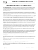
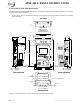
MNE-240 E-PANEL INSTRUCTIONS FRONT SIDE PW R Upper Mounting Bracket FAULT CHG S E LE C T I NV Inv erting O N /O F F DC 50.
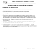
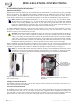
MNE-240 E-PANEL INSTRUCTIONS Figure 1, MNE-240 Series E-Panel Features 3.0 Installation Before installing, read the entire installation section to determine how you are going to install your E-Panel. The more thorough you plan in the beginning, the better your overall system needs will be met. A basic system diagram for the MNE-240 Series E-Panel is shown in Figure 2, MNE-240 Series E-Panel System Wiring Diagram. This diagram should be reviewed to assist you in planning and designing your installation.
MNE-240 E-PANEL INSTRUCTIONS Utility or Generator 120/240VAC Output AC Ground 120VAC Outlet IN V E R TE R Inverter AC Input Disconnect (30A) (AC In) ON ON OFF OFF Bypass Switch (50A) 0 A5 0 ON ON OFF OFF ON ON OFF OFF ON 120VAC Output 15A 240VAC Output 120VAC Output OFF AC Hot Out 2 OF F OF F ON AC Hot Out 1 ON ON AC Neutral ON OFF AC Hot In 2 OF F ON OF F OFF ON OF F ON O FF ON ON AC Hot In 1 OFF ON O FF ON ON OFF OF F ON OF F ON ON OF F ON ON O
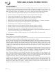
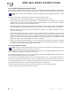
MNE-240 E-PANEL INSTRUCTIONS 3.3 Knockout sizes and Dimensions The dimensioned chassis drawing in figure 3 shows the location of the conduit knockouts, mounting holes and mounting brackets. • Knockouts on the top surface are directly in line with ones on the bottom surface for stacking units vertically. TOP VIEW UPPER CONDUIT KNOCKOUTS ARE MIRROR IMAGE OF BOTTOM KNOCKOUTS 4.67" 0.75 " 12.90" 22.37" 17.00" 4.17" INSIDE 1.13" (3/4 CONDUIT ) INSIDE 1.38" (1" CONDUIT ) 24.91" 26.45" INSIDE 0.
MNE-240 E-PANEL INSTRUCTIONS 3.4 Installing Optional Hardware Additional Breakers Additional AC circuit breakers can be installed per the manufacturer’s instructions on the open DIN Rail in the E-Panel. This DIN Rail has locations available for six additional 13mm wide AC and DC circuit breakers. These additional circuit breakers can be used for such things as: solar, wind or hydro charge controllers, DC ground fault protector, AC and/or DC distribution center and more.
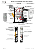
MNE-240 E-PANEL INSTRUCTIONS 3.5 Locating and Mounting the E-Panel Review Figure 6, MNE-240 Series E-Panel Mounted to determine the mounting space requirements for the E-Panel with the inverter/charger and any other optional equipment that may be mounted. Info: Do as much of the additional wiring as possible before hanging the E-Panel on the wall. Install the E-Panel in a location that meets the following requirements: • The E-Panel must be mounted vertically on a flat surface (such as a wall).
MNE-240 E-PANEL INSTRUCTIONS Ceiling 22.37" 22.23" 18.50" Top Mounting Bracket 16.00" 14.41" P WR FA U LT C H G IN V SELE CT Remote Remote Control Control CHARG ER I NVERTER SHO RE AG S M ETER SETUP TECH 24.91" Magnum Inverter/ Charger 26.
MNE-240 E-PANEL INSTRUCTIONS 3.6 Mounting the Inverter Before mounting the inverter to the chassis, complete all wiring that will be coming to and going from the E-Panel. Figure 7 shows additional wiring for adding lightning arrestors (top of enclosure), wiring circuit breakers for charge controllers (right side in the middle), tying down the remote control communication cable (left side), and connecting the GROUND bus-bar to the NEUTRAL bus-bar when this E-Panel is used as the main electrical panel.
MNE-240 E-PANEL INSTRUCTIONS 3.7 Wiring the E-Panel and Inverter Review the following information prior to wiring the E-Panel it is imperative that the following steps be taken to help reduce the risk of electric shock to you and damage to the E-Panel/inverter. 1. Disconnect the main AC panel that will feed the E-Panel (if using utility power) by switching off the main circuit breaker. Lock out the AC breaker box to ensure no one will accidentally turn the power on during the installation process.
MNE-240 E-PANEL INSTRUCTIONS AC CONNECTIONS AC HOT IN 1 (from Utility/ Generator) AC NEUTRAL connection AC HOT IN 2 (from Utility/ Generator) AC GROUND connection DC GROUND connection Battery Cable to Inverter Positive (+) connection Battery Bank Positive (+) connection Battery Bank Negative (-) connection AC CONNECTIONS Battery Cable To Inverter Negative (-) connection AC NEUTRAL connection AC HOT OUT 2 (to sub-panel or circuit breakers) AC HOT OUT 2 (to sub-panel or circuit breakers) AC HOT OUT 1
MNE-240 E-PANEL INSTRUCTIONS 3.9 DC Cable Wiring It is important to use the correct DC cable and corresponding circuit breaker to achieve maximum efficiency from the system and reduce fire hazards associated with overheating. See the MS-AE Series Owner’s Manual to determine the minimum DC cable size needed based on your inverter model and the total cable distance. Pre-DC Wiring Checklist • DC wires and cables should be tied together with wire ties or electrical tape approximately every 6 inches.
MNE-240 E-PANEL INSTRUCTIONS MidNite MNE-240 Series E-Panel Inverting DC 50.
MNE-240 E-PANEL INSTRUCTIONS 3.10 AC Wiring The full AC pass-thru capacity of the MS-AE Series inverter/charger is 30 amps for both AC legs (AC HOT 1 and AC HOT 2). To obtain the full pass-thru capability of the inverter and protect the inverter’s pass-thru relay, use a maximum 30 amp double-pole breaker, which corresponds to a cable size of #8 AWG (THHN) in conduit. If you are using other wire sizes, please refer to your local electrical code for breaker requirements.
MNE-240 E-PANEL INSTRUCTIONS Main Panel (Utility/Generator Input ) AC Output Wiring ON AC Input Wiring 120 /240 VAC from Main Panel to AC HOT IN and NEUTRAL Bus-bars OFF ON ON OF F OF F OFF ON ON OF F OF F ON OFF ON AC Output Wiring - a) Wire to an electrical sub -panel , OFF ON ON OF F O FF ON ON OFF ON OF F ON OFF or b) Use optional circuit breakers installed in the E-Panel.
MNE-240 E-PANEL INSTRUCTIONS MidNite MNE -240 Series E -Panel P WR Inverting DC 50.4 5A FA U LT CHG I NV SELECT O N /O F F CHARG ER O N /O F F I NVERTER SHO RE AG S M ETER SETUP TECH 30 ME-RC Remote Control 30 GROUND AC HOT IN (r ed) AC HOT IN ( black) AC HOT OUT ( black) AC HOT OUT (r ed) AC NE UTRA L (white ) MS-AE Series Inverter/ Charger 3.
MNE-240 E-PANEL INSTRUCTIONS 3.11 Final Installation Tidbits: Wiring the Inverter Remote Control Refer to figure 13 for the following steps: 1. Connect one of the RJ11 connector ends of the remote communication cable to the back of the remote; refer to the ME-RC owner’s Manual for specific information. 2. Route the other RJ11 connector end through the E-Panel and E-Panel door and connect to the inverter’s RJ11 REMOTE PORT (blue label).
MNE-240 E-PANEL INSTRUCTIONS 4.0 Start-up and Testing After the DC and AC wiring has been completed, a series of voltage checks should be performed to ensure the system wiring is correct. If any of the tests fail, recheck the AC wiring. Before beginning, ensure all circuit breakers pertaining to the E-Panel system are OFF, this includes: • all circuit breakers in the main panel from all AC sources (utility or generator, if any) feeding the E-Panel. • all circuit breakers in the sub-panel (if used).
MNE-240 E-PANEL INSTRUCTIONS A. Testing the Inverter AC Output Wiring (Inverter is ON , Utility and/or Generator power to E -Panel is OFF and the bypass switch is in the “INVERTER” mode ) AC Input AC Output 120VAC (+/- 3%) 120VAC (+/- 3%) 240VAC (+/- 3%) E-Panel with Left Hand Door AC Output 120VAC (+/- 3%) AC Input 120VAC (+/- 3%) 240VAC (+/- 3%) E-Panel with Right Hand Door B.
MNE-240 E-PANEL INSTRUCTIONS 5.0 Operation When 120/240 VAC power (Utility or Generator) is provided to the inverter/charger through the E-Panel, the battery charger function and internal transfer switch are enabled. This allows the batteries to be kept fully charged and pass incoming AC power through the inverter to power to the AC loads that are connected to the inverter.
MNE-240 E-PANEL INSTRUCTIONS BYPASS Mode: In the Bypass mode, the power from the utility (or generator) routes through the Inverter Bypass Switch directly to the sub-panel. This mode allows the AC power to “bypass” the inverter and continue powering the sub-panel loads if the inverter or batteries need to be serviced or removed. While in this mode, the sub-panel loads will not continue to be powered if utility power fails or the generator is turned off.
MNE-240 E-PANEL INSTRUCTIONS MIDNITE SOLAR INC. LIMITED WARRANTY MidNite Solar Power electronics, sheet metal enclosures and accessories MidNite Solar Inc. warrants to the original customer that its products shall be free from defects in materials and workmanship. This warranty will be valid for a period of five (5) years for all products except the MNKID Charge Controller which will be two (2) years.