
Magnum (MS4448 120/240VAC) MNE240 SeriesOwner's Manual


12 | P a g e 1 0 - 0 2 9 - 1 R E V : B
MNE-240 E-PANEL INSTRUCTIONS
3.6 Mounting the Inverter
Before mounting the inverter to the chassis, complete all wiring that will be coming to and going
from the E-Panel.
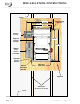
Figure 7 shows additional wiring for adding lightning arrestors (top of enclosure), wiring circuit
breakers for charge controllers (right side in the middle), tying down the remote control com-
munication cable (left side), and connecting the GROUND bus-bar to the NEUTRAL bus-bar when
this E-Panel is used as the main electrical panel.
Figure 7, Additional Wiring with E-Panel
Mounted
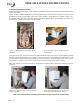
Figure 8, Securing the Inverter to the
E-Panel Door
As shown in figure 8, secure the inverter to the E-Panel door using six 6 mm x 20 mm taptite (thread
forming) pan head Phillips screws. These 6 mm screws require a #3 Phillips screwdriver. Use one
of these 6 mm screws to pre-tap threads into the steel doors extruded funnel holes. Ensure a ¼”
star washer is used with one of the 6 mm screws to bite through the powder coating.
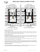
Once the inverter is secured to the door, lift it into the E-Panel hinge openings as shown in figures
9 and 10.
Figure 9, Lifting the door into the E-Panel
hinge openings
Figure 10, Ensuring door is in all three
hinge openings and moves freely
One of the best features of the E-Panel is that one person can do all the lifting.