
Magnum (MS4448 120/240VAC) MNE240 SeriesOwner's Manual


13 | P a g e 1 0 - 0 2 9 - 1 R E V : B
MNE-240 E-PANEL INSTRUCTIONS
3.7 Wiring the E-Panel and Inverter
Review the following information prior to wiring the E-Panel it is imperative that the following steps
be taken to help reduce the risk of electric shock to you and damage to the E-Panel/inverter.
1. Disconnect the main AC panel that will feed the E-Panel (if using utility power) by switching
off the main circuit breaker. Lock out the AC breaker box to ensure no one will accidentally turn
the power on during the installation process. If the AC panel does not have provision for locking
the breaker box, place a sign on the box and tape the door closed to warn others from opening
or turning on the AC panel.
2. Place the main DC shutoff breaker (DC disconnect) in the OFF position.
3. If additional breakers are installed, place them in the OFF position.
4. Turn the inverter bypass switch to the “BYPASS” position (see the label on the bypass switch).
Pre-Wiring Requirements
• All wiring and installations methods should conform to applicable electrical and building codes.
• Always check for existing electrical, plumbing or other areas of potential damage prior to
making cuts in structural surfaces or walls.
• Make sure all wires have a smooth bend radius and do not become kinked.
• Both AC and DC overcurrent protection must be provided in this installation.
• Use only copper wires with a minimum temperature rating of 75° C (176° F) to connect to the
wiring terminals.
• All wiring within the E-Panel enclosure, except low voltage control wiring, shall be rated at least
250V or a combination of 250V (e.g., 125V cable enclosed in 125V insulation/heat shrink).
• All wiring to the battery terminals should be checked periodically (once a month) for proper
tightness.
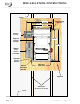
Install the Door Grommets
All wires that need to pass through the door of the E-Panel must
be routed through the provided serrated snap-in grommets. These
grommets help minimize wire insulation damage such as chafing,
which can be caused by constant rubbing when opening and
closing the door. A 3.5” plastic grommet is supplied and should
be snapped into the larger hole in the door as shown in figure 11.
The smaller 1” hole can be used for small signal wires (e.g. remote
communications wire, battery temperature sensor cable, etc.), but
no grommet is provided. It is important to route the wires so the
door closes freely without undue force.
Grounding
Figure 11, Installing 3.5”
Grommet in the Door
The E-Panel should be connected to a grounded, permanent wiring system.
DC Grounding - The negative battery conductor should be bonded to the grounding system at
only one point in the system. The size for the conductor is usually determined by the size of the
DC overcurrent protection (DC disconnect) per the NEC/CEC.
If the MNDC-GFP ground fault protector is installed, DO NOT connect battery negative to ground
- this connection is accomplished by the MNDC-GFP. Any additional DC grounding will make the
MNDC-GFP inoperative.
AC Grounding - The AC neutral and ground should only be bonded at the main service panel for
the AC system.