
Magnum (MS4448 120/240VAC) MNE240 SeriesOwner's Manual


15 | P a g e 1 0 - 0 2 9 - 1 R E V : B
MNE-240 E-PANEL INSTRUCTIONS
3.9 DC Cable Wiring
It is important to use the correct DC cable and corresponding circuit breaker to achieve maximum
efficiency from the system and reduce fire hazards associated with overheating. See the MS-AE
Series Owner’s Manual to determine the minimum DC cable size needed based on your inverter
model and the total cable distance.
Pre-DC Wiring Checklist
• DC wires and cables should be tied together with wire ties or electrical tape approximately every
6 inches. This helps improve the surge capability and reduces the effects of inductance, which
improves the inverter waveform and reduces the wear of the inverter’s filter capacitors.
• The DC cables/wires must be color coded with colored tape or heat shrink tubing: RED for positive
(+); WHITE for negative (-); and GREEN for DC ground.
• It is important to route the cables so the doors close freely without undue force.
• The inverter uses 5/16” bolts and requires cables having ring terminal lugs with a 5/16 hole.
Torque these bolts between 10 to 12 foot-pounds.
• To ensure the maximum performance from the inverter, all connections from the battery bank
to the inverter should be minimized. Any additional connection may contribute to additional
voltage drops and may loosen during use.
• The DC cables must be a fine strand super flexible, such as Cobra cable (or equivalent) and
be approved for residential wiring per the NEC (THW for example).
Caution: The inverter is NOT polarity protected; the battery’s negative and positive terminals
MUST be correctly connected to the inverter’s negative and positive terminals before turning
ON the DC battery breaker or damage will occur. The inverter’s warranty doesn’t cover
repair to the inverter from this damage.
Caution: The battery bank voltage MUST match the inverter’s required DC voltage (i.e.
48vdc battery for a 48vdc inverter) or the inverter may be damaged.
Info: After making the battery connections, cover the outside of the connection with
petroleum jelly or another form of battery terminal anticorrosive grease. Do not put anti-
corrosion grease between the terminal and the battery cable.
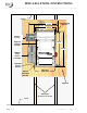
Connecting the DC cables
Refer to figure 13 for connecting the cables in the following steps:
Info: Figure 13 shows the battery cables coming from below, but the E-Panel has knockouts
that allows the cables to come from the sides or back.
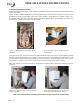
Connecting the Inverter DC Cables
1. Route the pre-wired positive (+) battery cable from the DC disconnect in the E-Panel through the
grommet/door and connect to the positive battery terminal on the inverter.
2. Route the pre-wired negative (-) battery cable from the DC shunt in the E-Panel through the
grommet/door and connect to the negative battery terminal on the inverter.
Connecting the Battery DC Cables
1. Route a DC cable from the negative (-) battery terminal of the battery bank through the
conduit/E-Panel knock-outs and connect to the open terminal on the DC shunt.
2. Route a DC cable from the positive (+) battery terminal of the battery bank through conduit
and connect to the bottom (source) side of the DC disconnect.
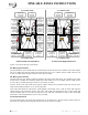
Connecting the Battery Temperature Sensor (BTS)
1. Connect the BTS ring terminal end to the negative terminal on the battery bank. Route its cable
from the battery bank through either the 3.5” or 1” hole in the E-Panel door and connect to the
inverter’s RJ11 BTS PORT (yellow label).