
Magnum (MS4448 120/240VAC) MNE240 SeriesOwner's Manual


17 | P a g e 1 0 - 0 2 9 - 1 R E V : B
MNE-240 E-PANEL INSTRUCTIONS
3.10 AC Wiring
The full AC pass-thru capacity of the MS-AE Series inverter/charger is 30 amps for both AC legs
(AC HOT 1 and AC HOT 2). To obtain the full pass-thru capability of the inverter and protect the
inverter’s pass-thru relay, use a maximum 30 amp double-pole breaker, which corresponds to a
cable size of #8 AWG (THHN) in conduit. If you are using other wire sizes, please refer to your
local electrical code for breaker requirements.
Pre-AC Wring Checklist
• AC input to the inverter requires a maximum 30 amp circuit-breaker to each of the inverter’s
AC Hot inputs. If the dual-pole AC input disconnect in the E-Panel is rated for 30 amps, it will
meet this requirement.
• AC Loads powered by the inverter will need to installed into an electrical sub-panel; or optional
branch-rated breakers may be may be installed in the E-Panel and used to power these AC
loads.
• Always use properly rated circuit-breakers. If using an electrical sub-panel, circuit breakers
can be moved from the main electrical panel to the sub-panel only if the breakers are also
listed to be installed in the sub-panel.
• AC wiring must be no less than 10 AWG (5.3 mm
2
) gauge copper wire and be approved for
residential wiring per the NEC (THHN as an example).
Connecting the AC wires
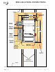
Connecting E-Panel AC Input/Output Wires (refer to Figure 12 and 14 for the following steps):
1. Route two wires [AC hot 1 (black/L1) and AC hot 2 (red/L2)] from a double-pole circuit breaker
in the main panel and connect to the AC HOT IN 1 and AC HOT IN 2 bus-bars in the E-Panel
respectively.
2. Route a wire from the neutral bus-bar in the main panel and connect to the NEUTRAL bus-bar
in the E-Panel.
3. Route a wire from the ground bus-bar in the main panel and connect to the GROUND bus-bar
in the E-panel.
4. Route wires from the AC HOT OUT 1 (black/L1), AC HOT OUT 2 (red/Leg 2), NEUTRAL and
GROUND bus-bars in the E-Panel and either connect to: A) the sub-panel, or B) to each individual
circuit breaker if installed in the E-Panel.
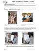
Connecting to the Inverter AC terminals
Before connecting the wires to the inverter’s AC terminal block: 1. Ensure the wires are routed
through the 3.5” grommet in the door; and 2. Establish the correct length of wire by opening and
closing the door, then cut back the wires as required.
Info: Remove the AC access cover to expose the AC terminal block in the MS-AE Series
Inverter as described in owner’s manual.
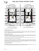
For the following steps, refer to figure 4-5 to locate the #8 AWG wires in the E-Panel:
1. Connect the black wire labeled AC HOT OUT to the inverter’s AC HOT OUT 1 terminal.
2. Connect the red wire labeled AC HOT OUT to the inverter’s AC HOT OUT 2 terminal.
3. Connect the white wire from the NEUTRAL bus-bar in the E-Panel to either one of the inverter’s
AC NEUTRAL terminals.
4. Connect the black wire labeled AC HOT IN to the inverter’s AC HOT IN 1 terminal.
5. Connect the red wire labeled AC HOT IN to the inverter’s AC HOT IN 2 terminal.
Info: A ground wire from the E-Panel to the inverter AC ground terminal is not required,
because the inverter is sufficiently grounded through the E-Panel to the permanent ground
system. A ground wire may be connected from the GROUND bus-bar in the E-Panel to the
inverter’s AC GROUND for additional redundancy.