
Magnum (MS4448 120/240VAC) MNE240 SeriesOwner's Manual


20 | P a g e 1 0 - 0 2 9 - 1 R E V : B
MNE-240 E-PANEL INSTRUCTIONS
3.11 Final Installation Tidbits:
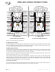
Wiring the Inverter Remote Control
Refer to figure 13 for the following steps:
1. Connect one of the RJ11 connector ends of the remote communication cable to the back of the
remote; refer to the ME-RC owner’s Manual for specific information.
2. Route the other RJ11 connector end through the E-Panel and E-Panel door and connect to the
inverter’s RJ11 REMOTE PORT (blue label).
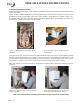
Additional Accessory Wiring
Before attaching the DC cover to the inverter end, if you have any of the following inverter
accessories, then you will also need to route their connecting cables through the E-Panel (and
pass through the small snap-in grommet in the door) to the RJ11 Ports on the inverter:
• Automatic Generator Start Controller (ME-AGS) for automatic generator starting an stopping.
• Battery Monitor (ME-BMK-NS) for determining your batteries State of Charge.
• Simple ON/OFF adapters (ME-RSA, ME-RSA-M) that allow the inverter to be remotely turned
on/off.
See the appropriate accessory owner’s guide or further information about the installation and
configuration of these accessories.
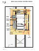
Installing Inverter Shield/Covers
Refer to figure 1 to identify the following components:
Upper Shield - Attach the upper shield to the E-Panel door using three 10-32 x 3/8” machine
screws and kepnuts.
DC Cover - Attach the DC cover using four 10-32 x 7/16” taptite screws and at least one #10
internal tooth star washers.