
MNEPV - Series Circuit Breakers Data Sheet

low voltage
QY-SERIES-DAT
APR 2015
Data Sheet
Page 3 of 8
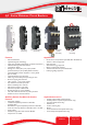
QY - Series Miniature Circuit Breakers
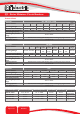
Example Code: QY---A-3(13)-D-U2-150A-B0-----Z
Group 1 2 3 4 5 6 7 8 9 10 11 12
Requirement
QY
Frame
Switch /
Neutral
Auxiliary
Triple
pole
13 mm
module
width
DIN Rail
Medium
delay
curve U2
Current
Rating
150 A
Voltage
80 V DC
No Shunt
Trip
Future
use
Parallel
bridged
(by
customer)
Long Code QY - A 3 (13) D U2 150A B0 - - Z
Long Code
Group 1:
Frame Type
Code Description Comments
QY 13 mm wide Miniature Circuit Breaker UL 489A, IEC / EN 60947-2, VDE, CE, CCC
Group 2:
Switch/Neutral
Code Description Comments
- Not applicable Overload poles do not have any further coding
Group 3:
Auxiliary
Code Description Comments
- Not applicable Use this code if no Auxiliary used
A Auxiliary Switch (1 x Aux in 1 module) 6.5 mm module tted on right-hand side (DIN & Dual Mount)
T Trip Alarm (1 x Trip Alarm in 1 module) 6.5 mm module tted on right-hand side (Dual Mount only)
AT Auxiliary Switch + Trip Alarm combo (combined in 1 module) 6.5 mm module tted on right-hand side (Dual Mount only)
Group 4:
No of Poles
Code Description Comments
1 Single pole
2 Double pole
3 Triple pole
4 Four pole
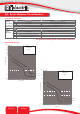
Group 5:
Module Width
Code Description Comments
(13) 13 mm module width 13 mm per pole
Group 6:
Mounting
Code Description Comments
D DIN rail mount – 45 mm Escutcheon, grey body DIN mount supplied in grey only
DM Dual mount – 57 mm Escutcheon, black body Dual mount supplied in black only
Group 7:
Time Delays
Code Description Instantaneous Trip Point (x In) Comments
1 Long time delay, high instantaneous trip 10 – 20 Orange handle
9 Long time delay 7 – 12 White handle
U2 Medium time delay 5 – 10 White handle
U3 Short time delay 3 – 5 White handle
OP Instantaneous None White handle
Group 8:
Current
Ratings
Code / Description Comments
0.1, 0.2, 0.3, 0.5, 1, 2, 3, 4, 5, 6, 7, 8 ,9, 10, 12, 15, 16, 20, 25, 30, 32, 35, 40, 45,
50, 60, 63, 70, 80, 90, 100, 120, 125, 150, 200 A
Ratings available vary depending on certication, bridging
conguration and voltage. (See comments in Group 9)
* Other ratings are available as special orders. Check availability.
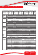
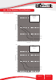
Group 9:
Voltage
(see diagram
on page 7)
Code Voltage Description Comments
B0 80 V DC Not polarity sensitive
0.1 - 63 A 1 pole, 0.1 - 50 A 2 pole, 60 - 100 A 2 pole parallel
(80 V DC), 30 - 100 A 2 pole parallel (125 V DC),
110 - 150 A 3 pole parallel, 200 A 4 pole parallel
(ratings available vary depending on certication)
B1 125 V DC Polarity sensitive. Positive bottom.
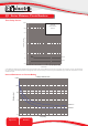
B2 250 V DC
2 poles in series bridged (2 x 125 V)
Positive = pole 1 bottom
0.1 - 50 A 2 pole series bridged at the top (by customer)
pole 1 (-) to pole 2 (+)
B3 250 V DC
2 poles in series bridged (2 x 125 V)
Positive = pole 1 bottom
0.1 - 50 A 2 pole series bridged at the top (factory tted)
pole 1 (-) to pole 2 (+)
B4 600 V DC
4 poles in series bridged (4 x 125 V)
Positive = pole 1 bottom
0.1 - 20 A 4 pole series bridged (factory tted)
As per wiring diagram printed on unit
T1 125 V DC Polarity sensitive. Positive top.
0.1 - 63 A 1 pole, 0.1 - 50 A 2 pole, 30 - 100 A 2 pole parallel,
110 - 150 A 3 pole parallel, 200 A 4 pole parallel
T2 250 V DC
2 poles in series bridged (2 x 125 V)
Positive = pole 1 top
0.1 - 50 A 2 pole series bridged at the bottom (by customer)
pole 1 (-) to pole 2 (+)
T3 250 V DC
2 poles in series bridged (2 x 125 V)
Positive = pole 1 top
0.1 - 50 A 2 pole series bridged at the bottom (factory tted)
pole 1 (-) to pole 2 (+)
T4 600 V DC
4 poles in series bridged (4 x 125 V)
Positive = pole 1 top
0.1 - 20 A 4 pole series bridged (factory tted)
As per wiring diagram printed on unit
Continues on page 4