
MNEPV - Series Circuit Breakers Data Sheet

low voltage
QY-SERIES-DAT
APR 2015
Data Sheet
Page 7 of 8
11.7
[0.461]
18.0
[0.709]
37.8
[1.5900]
18.0
[0.709]
35.5
[1.400]
57.0
[2.244]
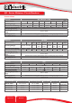
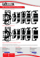
TEST BUTTON
(on Trip Alarm only)
AUXILIARY/ TRIP ALARM (AT)
CONNECTING TERMINALS
DETAIL (COMMON TO ALL)
Q-AUX
RoHS
AUXILIARY SWITCH
TRIP ALARM S WITCH
EN/IEC 60947-5-1
110 VDC : 0,5A
240 VAC : 6A
15
18
16
11
12
14
Uimp = 2.5kV
Icw = 0. 1kA
UTIL. CAT. AC12/DC12
POLLUTION DEGREE 3
110 VDC : 0,5A
240 VAC : 6A
S
A005438
D
E
V
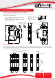
All dimensions in mm [ inch ]
Tolerance ± 0.2 unless otherwise specified
Typical outline for an Auxiliary module
attached to a Dual mount single pole
Circuit Breaker
14
12
11
15
18
16
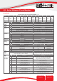
Circuit Diagram when the Circuit
Breaker is in the “OFF” position
Trip Alarm Switch
15
16
18
Auxiliary Switch
11
12
14
97.2
[3.827]
69.8
[2.750]
6.5
[0.256]
6.0
[0.236]
0.8
[0.0315]
1.4
2.80
[0.110]
6.8
[0.270]
2.3
[0.090]
0.5
[0.020]
45°
0.055][
19.3 ± 0.3
[0.760 ± 0.012]
NC
NO
C
C
NC
NO
Typical outline of Auxiliary Switch / Trip Alarm
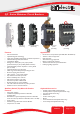
QY - Series Miniature Circuit Breakers
Auxiliary available (6.5 mm module width) to match the unit to which it is attached.
Available types as listed in Group 3:
• Type T - Trip Alarm as shown in outline drawings
(tted on a Dual mount product)
• Type AT - Auxiliary Switch + Trip Alarm (as shown)
• Type A - Auxiliary Switch
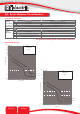
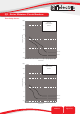
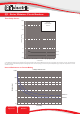
Polarity identication
Pole 1
(Positive Bottom)
Pole 1
(Positive Top)
Positive Bottom
Positive Top
Polarity
Marking
Bottom (Load
side)
Wire link or busbar
Series Bridged Parallel Bridged
Top (Line side)
4 Poles 2 Poles 1 Pole 1 Pole
+
-
+
- - -
+
-
-
+
-
+ + +
-
+
Diagram identifying the polarity of 125 V DC products in reference to Group 9 on page 3. Devices are shown viewed from the
front. Series devices (standard) - each pole is opposite polarity from the next pole on the left (bridged “-” to “+”). Parallel devices
- each pole has the same polarity (bridged “+” to “+”, “-” to “-”).