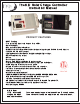
The KID Solar Charge Controller Instruction Manual PRODU CT FEAT U RES • MPPT Tracking . • True paralleling - Inputs and Outputs for two KIDs . • Up to 1 50V input. • Now available with Auto Gen-Start. • MidNite's exclusive HyperVOC extends the input voltage beyond 1 50 VOC for cold climates . • 1 2V, 24V, 36V, 48V battery output. • Lighting Controller: dusk+hours, daylight and night-light settings . • Up to 30 amps battery output. • No fan . • Reverse polarity protected .
The KID Solar Charge Controller Instructions IMPORTANT SAFETY INSTRUCTIONS SAVE THESE INSTRUCTIONS - THESE INSTRUCTIONS CONTAIN IMPORTANT SAFETY AND OPERATING INSTRUCTIONS FOR THE KID CHARGE CONTROLLER MODEL NUMBERS MNKID-B, MNKID-W, MNKID-M-B, MNKID-M-W, MNKID-C1 D2. If you do not fully understand any of the concepts, terminology, or hazards outlined in these instructions, please refer installation to a qualified dealer, electrician or installer.
The KID Solar Charge Controller Instructions INSTRUCTIONS DE SÉCURITÉ IMPORTANTES CONSERVER CES INSTRUCTIONS - CES INSTRUCTIONS CONTIENNENT DES INFORMATIONS IMPORTANTES POUR UTILISER LE MIDNITE SOLAR THE KID CHARGE CONTROLLER (RÉGULATEUR DE CHARGE) MODELES MNKID-B, MNKID-W, MNKID-M-B, MNKID-M-W, MN KIDC1 D2 EN TOUTE SÉCURITÉ. Avant l’utilisez cet appareil lis et comprends toutes les instructions et avertissements.
The KID Solar Charge Controller Instructions Agency Approvals The KID is ETL listed to: UL 1 741 ISSUE:201 0/01 /28 ED:2 INVERTERS, CONVERTERS, CONTROLLERS AND INTERCONNECTION SYSTEM EQUIPMENT FOR USE WITH DISTRIBUTED ENERGY RESOURCES CSA C22.2#1 07.1 ISSUED: 2001 /09/01 ED: 3 (R2011 ) GENERAL USE POWER SUPPLIES . UL 458 ISSUED:2006/04/1 9 ED:5 REV:201 0/03/1 8 UL STANDARD FOR SAFETY POWER CONVERTERS/INVERTERS AND POWER CONVERTER/INVERTER SYSTEMS FOR LAND VEHICLES AND MARINE CRAFTS . CSA C22.2#1 07.
The KID Solar Charge Controller Instructions Table of Contents Warnings.............................................................................................. 2 Agency Approvals................................................................................ 4 Stickers................................................................................................ 7 The KID Dimensions............................................................................ 11 Mounting The KID......................
The KID Solar Charge Controller Instructions The parts included in the hardware kit provide great flexibility for installing The KID in many different locations. Included Hardware kit 9-61 4-1 90° 1 /2" snap-in Conduit adapter (2) (Marine hardware kit only) There are straight and right angle fittings for flex conduit as well as a strain relief for power wires and a split grommet for data wires.
The KID Solar Charge Controller Instructions Sticker Identification 1 . Warning-ignition protected / CID2*. 2. Equipment grounding terminal. 3. Connection sequence. 4. Do not overtighten. 5. Shipping serial number. 6. Negatives Separate. 7. Model Number. 8. Caution Voltage Present. 9. Aux Output Ratings. 1 0. CE. 11 . Don't touch uninsulated. 1 2. Charge battery types. 1 3. Start up info. 1 4. Cautions. 1 5. Protect from rain. 1 6. Arcs and sparks - Français. 1 7. Arcs and sparks - English. 1 8. Torque.
The KID Solar Charge Controller Instructions Sticker Placement Due to the large number of required warnings it is easy to begin to overlook them. Some of the warnings are actually quite important and good knowledge for the installer and user. All required labels are supplied. You will find a label identifier on the previous page. The placement guide below shows where each label goes. Please take the time to read and understand each label as you place it on the unit.
The KID Solar Charge Controller Instructions MNKID-C1 D2 Sticker placement: MNKID-C1 D2 Sticker placement is slightly different than the other models. Sticker location is indicated below. Refer to sticker ID chart on page 7.
The KID Solar Charge Controller Instructions Additional Stickers: In Canada CSA 22.2 No. 1 07.1 -01 requires certain information to be visible while the unit is in operation. To satisfy this requirement some additional stickers have been provided for the wall mount adapter. These stickers have the same information as those already on The KID.
The KID Solar Charge Controller Instructions Mounting The KID: There are three methods of mounting available for The KID: 1 . In wall mounting. This is very useful for RV’s, some boats and cabins or just about anywhere you want a built in look. You will need to ensure that the wall is not so thick as to obstruct the wiring that enters through the bottom surface of The KID. The conduit wire holes in the bottom of the casting are 0.28” (7mm) away from the back mounting flange.
The KID Solar Charge Controller Instructions 2. Surface mount. Most KIDs come pre-installed into the wall mount bracket. These instructions apply to KIDs that are field installed into the wall mount bracket. The KID can be mounted on a wall using the supplied wall mount adapter. As a minimum you will need to supply ½” strain reliefs to secure the wires to the casting. Regular metal strain reliefs are available at any hardware or electrical store.
The KID Solar Charge Controller Instructions 3. Marine mount. The third way to mount The KID is with the Marine Mount Bracket. MNKID-M-BKT-W (White) or MNKID-M-BKT-B (Black) Marine Mounting Brackets. The Marine KID and Marine Bracket are certified to UL 458 marine vibration standards. This bracket comes standard with Marine versions. There are two metal pieces that come with the Marine Mount Bracket. A collar that mounts to The KID and the Marine mounting bracket base.
The KID Solar Charge Controller Instructions Optional rain Shield . Required for approved marine applications. The KID shown with the optional Rain/Drip Shield. The rain/drip shield is required for code compliant marine applications. The addition of the rain/drip shield does not make The KID weatherproof. Install The KID where it will be protected from rain, spray, snow or other moisture.
The KID Solar Charge Controller Instructions The KID Main Electrical Connections The following pages contain wiring instructions, diagrams and system images. WARNING: Unlike some controllers The KID uses the PV negative and Battery negative to measure current so they must stay isolated from each other. PV negative must NOT be electrically common in any way with battery negative or undesired operations will occur. Remove the back cover.
The KID Solar Charge Controller Instructions Grounding Lug Required for UL458 Marine and RV standard compliant installations. Grounding points are provided inside and on the back of The KID. This ground lug is necessary to satisfy the requirements of UL458 Marine and RV standard. Drill a 7/32" (5.5mm) hole approximately where shown. Make sure that you have room inside the unit for screwhead clearance. Install the external ground lug as shown below with the hardware supplied.
The KID Solar Charge Controller Instructions Wiring the marine KID Centered directly above the ½” conduit holes you will find the main 30 amp 6 position terminal block. This is where you will connect PV input, loads (if any), and the battery bank. The battery bank should use 1 0AWG wire (5.26mm2). Wiring runs from the battery bank should be as short as possible. On the included wiring diagrams you will notice an external 30 amp circuit breaker in series with the battery plus wire.
The KID Solar Charge Controller Instructions Aux input/output wiring: This 3 position terminal block is the aux input/output. Functions such as Auto Gen Start, Low Battery Disconnect or the WhizBang Jr are connected here. As new firmware features are added they will be available at http://www.midnitesolar.com/firmwareIndex.php Small Terminal Block AUX + AUX WBJR The top position is AUX + . The middle position is AUX -. See page 39. The bottom position is where the purple wire from the WBJr.
The KID Solar Charge Controller Instructions AUX/ WBJr Terminal Block. To insert a wire: Strip 5/6" (8mm) and press into the terminal block until it is seated. Gently tug to ensure the wire is fully installed. To remove the wire: Gently press down on the white plastic next to the wire while gently pulling the wire out. Mounting and Wiring with the wall mount bracket: - + PV - + LOAD - + BATTERY IMPORTANT! Input, output, and load negatives must be isolated. They are not internally connected.
The KID Solar Charge Controller Instructions Chassis Ground connection The screw, nut, and terminal for grounding the chassis are included on all models. The chassis ground (equipment ground) is required in an NEC compliant system. The chassis of The KID is isolated from all internal KID circuitry. Wall mount versions have a short wire pre-installed in this location. It can be found in the wiring area of the wall mount.
The KID Solar Charge Controller Instructions MNBTS Battery Temperature sensor Note: Do not use the BTS with the stacking jumpers installed. Standard on Marine versions, optional on all others. The published ratings of most batteries are made at 77 degrees F (25°C). Mother nature as well as man doesn’t always allow the ambient temperature to hover around 25°C while charging batteries.
The KID Solar Charge Controller Instructions Stacking Jumpers Master Stacking Port Jumper settings for stacking (Twin Mode): Slave Stacking Port USB Connector do not use in hazardous environment In the upper right corner of the circuit board there are two positions for placing jumpers. If not stacking (only one KID) or stacking two KIDs leave the jumpers off. The jumpers may be placed on one pin to be saved for later use.
The KID Solar Charge Controller Instructions 23 | Page 1 0-268-1 REV P7
The KID Solar Charge Controller Instructions 24 | Page 1 0-268-1 REV P7
The KID Solar Charge Controller Instructions Initial Set-Up and Use These instructions are for firmware revision 1 856. New features are added frequently. Now that your KID is all wired up, solar panels in place and connected, battery bank installed and any loads connected, it is time to turn things on. Get a digital meter. Good low cost meters are readily available so there is no excuse to not have one. You will need one if support is ever required. Check list: Make sure all breakers are off.
The KID Solar Charge Controller Instructions The next set of screens are where you select battery type. Selecting the applicable battery type sets some important parameters that are specific to different battery chemistries. The first choice is Flooded. Use the up and down arrows to see all the choices. Listed below.
The KID Solar Charge Controller Instructions Ba t t e r y Ab s o r b 14. 3 Vo l t s When the absorb screen appears, use the up/down arrow to adjust absorb voltage. Consult your battery manufacturer for their recommended settings. There is no such thing as one setting that fits all flooded or AGM etc. batteries. Different manufacturers have different requirements. Differences may be subtle, but The KID is capable of very fine adjustment. There is no reason to guess as to these important settings.
The KID Solar Charge Controller Instructions STATUS BUTTON/SCREENS: The KID has several status display screens showing voltage, charge mode, temperatures, currents, and voltages. These screens are displayed any time that the LCD is on and you are not in a menu. If you press the STATUS button the following screens will be displayed. The first screen is displayed by default and the others are available by pressing the right arrow. The left arrow will step back through the status display screens. 9.
The KID Solar Charge Controller Instructions The KID has several L.E.D.s to indicate modes and errors. RFC - Received Full Charge. The battery has received a full charge in the last week. 1 WK - One Week. It has been more than one week since a full charge. - IN AGS Mode indicates generator running. 2WK - Two Weeks. It has been more than two weeks since a full charge. FLT - Float. The battery has reached float stage. The KID's L.E.D.s. OVR - Limit.
The KID Solar Charge Controller Instructions MAIN MENUS: The KID has 7 MAIN MENU headings. This section deals with the MAIN MENU headings only. Each of the 7 main menus is explained in detail on the following pages. Press the MENU/BACK key. This button takes you to all of the Main Menus. Main menus are something you want to become familiar with. No matter where you are at in any menu, you can always get to the Main Menus by pressing the MENU\BACK button once or twice.
The KID Solar Charge Controller Instructions Manual EQ- Manual Equalize it will do a single EQ cycle on the batteries if enough power is available from the solar source. Auto EQ- Auto Equalize allows the batteries to go through an EQ cycle in the days interval programmed in the unit, defaults to 30 days, Days can be adjusted by the user for the required interval for the specific batteries. Day count will be reset back to day 0 every time the unit loses power.
The KID Solar Charge Controller Instructions Advanced Battery Settings: Located under the “Battery” menu a submenu labeled “Advanced ”. This menu contains advanced charge settings. EndAmps: Best results are obtained when a Whiz Bang Jr. (Sold Separately) is connected to The KID. End Amps refers to the amount of current flowing to the batteries. When End Amps are set, this function will act as a secondary termination to the absorb timer.
The KID Solar Charge Controller Instructions Load Menu: Lighting Controller The KID has a fully adjustable, intelligent lighting controller built in. It can turn lighting on at dusk for a select number of hours, turn it off for a length of time and then back on for a programmable number of hours before dawn. All time functions are fully adjustable, allowing users to save valuable energy.
The KID Solar Charge Controller Instructions Load Control Modes The load control output is a very versatile feature. Some of the basic uses are explained here. ● Manual Mode - The load can be turned on and off manually from the load menu. The load can also be set to disconnect when the low voltage disconnect setting is reached. ● Dusk + Time - In this mode the load is turned on at dusk. The load then remains on for the amount of time selected.
The KID Solar Charge Controller Instructions Load Functions / Setup -FUNC: Manual - ON/OFF - This Mode can be turned On or Off by the user Manually, and the Load circuit will act accordingly, this Mode can be Used with the Low Battery Disconnect safety monitoring. To use Manual Mode: • From the Status Menu: Press Menu Back • Scroll to the Right and select Load and Press Enter • Select FUNC: Manual • Press the Right button to *ON - The load will turn on and stay on until turned off.
The KID Solar Charge Controller Instructions -FUNC: PWM Divert – OFF/AUTO – This function will divert excess power to the load when extra power is available and it will maintain 3 stage battery charging. There are 2 parameters that can be adjusted when Pressing the SETUP button; Offset and Width Offset: This is measured in voltage and refers to an offset from the current battery voltage Set point. For example, if the battery charging stage is Absorb, then the offset is taken from the Absorb set point.
The KID Solar Charge Controller Instructions -FUNC: Toggle Test – OFF/AUTO – This Mode is for testing purposes only, it will turn the load On and Off at twice per second. -FUNC: LVD Alarm – OFF/AUTO - This mode will turn on if the battery voltage goes below the AlrmON set point and turn OFF if it goes above the AlrmOFF Set point.
The KID Solar Charge Controller Instructions • • • • Press the Setup button If OFF appears under the names Lowbatt and Reconn it means the feature is currently disabled. Press the Right button to enable the function, now two numbers will appear under the names Press the Left, Right, Up, and Down keys to adjust the voltages as needed for your battery type Input Menu: ADJ UST MPPT MODE L OAD < I NPUT > AUX The INPUT MENU is where you turn charging on and off.
The KID Solar Charge Controller Instructions Press the right arrow to advance to the AUX MAIN MENU . SET UP AUX F UNCT I ON L OAD < AUX> MI SC The AUX menu is where you set up various auxiliary input and output functions such as Auto Genstart, Low Battery Disconnect and the Whizbang Jr. Battery status monitor. Note: Mode must be manually turned ON after changing the mode. To turn the Mode on highlight the OFF under ON/OFF and switch it to ON. Press the Save button to save this change.
The KID Solar Charge Controller Instructions FUNC: LBD Low OFF/AUTO - Enable/Disable/Setup Low Battery Disconnect High • • • • • • • From the Status Menu: Press Menu Back Scroll to the Right and select AUX and Press Enter Select FUNC:LBD Low Press SETUP button to set the AlrmON Voltage. scroll to the right to set AlrmOFF Voltage. Press the Save Button. Press the Right arrow button to Auto.
The KID Solar Charge Controller Instructions PC- KID PC Mode: Use this mode with a serial terminal program in a PC to display the following data: •Displayed Battery Voltage •Displayed PV Voltage •Displayed Output in Watts •KWHs produced •Amp Hours Produced •Battery Temperature •Whiz Bang Jr. Current •Battery state of charge •Whiz Bang Jr. Amp Hours Remaining Select and save PC Comm to enable this mode. Data is sent once a minute.
The KID Solar Charge Controller Instructions To change nitelite VOC: • • • • • • Press main Menu Scroll to the right then select TECH and press Enter Select Calibrate and press Enter Press the right arrow until Night Light on PV Sensitivity is on the top line of the LCD Use the Up and Down buttons to adjust to the desired setting Press the SAVE button to keep the settings. Reset to factory defaults.
The KID Solar Charge Controller Instructions Auto Gen Start Important! Do Not Exceed 1 2VDC at 1 00 mA Relay Drive Use Normally Open (N.O.) Contacts Auto Gen Start (AGS) This function will try to start the Generator and while monitoring battery voltage to assure the generator is charging. If not, it will signal the generator to shut down to conserve fuel. Generator On at: Battery voltage level that will trigger the signal to start the generator.
The KID Solar Charge Controller Instructions Setting up The KID for use with a Whiz Bang Jr. (Sold separately) State Of Charge: The KID, in conjunction with the Whiz-Bang JR. creates a very accurate battery State Of Charge meter within The KID. There is some set-up before using the WBJr and it will be necessary to enter values for Battery bank size in Amp-Hours, battery efficiency, Battery temperature compensation reference and percentage of change per degree C.
The KID Solar Charge Controller Instructions Password protected settings: UL standards mandate that only qualified people be allowed to change critical settings. We have determined that people that have read and understood this much of the manual are qualified to change critical settings. Changing some of the settings available on The KID can result in hazardous conditions. If you do not fully understand these functions and features contact your dealer.
The KID Solar Charge Controller Instructions LED MODE: Located under the MISC menu, the LED mode can be set to several different modes, some useful and some just for fun. NRML: this mode will employ all the available LEDs as indicators, The top 3 LEDs refer to the Battery Capacity Meter function on The KID that indicates to the user the current battery status at a glance . The FLT LED will come on when the unit goes to Float. It will blink Slowly when the unit goes to Float MPPT.
The KID Solar Charge Controller Instructions Wiring Diagrams 1 2 Volt System with two solar panels in series Important! Both the input and output negatives must be connected to their own separate terminals. Tying them together will cause inaccurate current readings and possible damage to the unit. 1 0-268-1 REV P7 47 | Page Important! Both the input and output negatives must be connected to their own separate terminals.
The KID Solar Charge Controller Instructions 24 Volt System with two solar panels in series Important! Both the input and output negatives must be connected to their own separate terminals. Tying them together will cause inaccurate current readings and possible damage to the unit. 1 0-268-1 REV P7 48 | Page Important! Both the input and output negatives must be connected to their own separate terminals. Tying them together will cause inaccurate current readings and possible damage to the unit.
The KID Solar Charge Controller Instructions 24 Volt System with two strings of two panels Important! Both the input and output negatives must be connected to their own separate terminals. Tying them together will cause inaccurate current readings and possible damage to the unit. 1 0-268-1 REV P7 49 | Page Important! Both the input and output negatives must be connected to their own separate terminals. Tying them together will cause inaccurate current readings and possible damage to the unit.
The KID Solar Charge Controller Instructions 48 Volt System with two strings of three panels The string sizing tool is at www.midnitesolar.com Important! Both the input and output negatives must be connected to their own separate terminals. Tying them together will cause inaccurate current readings and possible damage to the unit. 1 0-268-1 REV P7 50 | Page Important! Both the input and output negatives must be connected to their own separate terminals.
The KID Solar Charge Controller Instructions HyperVOC Why do you need HyperVOC? PV panels can put out full voltage even in very low light conditions, such as first light just before dawn. These low light levels do not have enough intensity to produce current flow, so the controller is not producing power at this point. This voltage is known as Open Circuit Voltage or Voc. Colder ambient temperatures cause solar panels to have higher open circuit voltages.
The KID Solar Charge Controller Instructions Example of an available Pre-Wired System Pre-wired system with integrated KID charge controller. Accessories Below are optional accessories and accessory kits. MNKID-BREAKER-30A 30 Amp replacement circuit breaker for The KID.
The KID Solar Charge Controller Instructions Accessories Continued MNKID-ASSY-KIT-B (Black) or MNKID-ASSY-KIT-W (White) Accessory kit Kit includes: Black or white mounting bracket Flexible conduit Straight and 90° Conduit fittings MNBTS Battery temperature sensor Hardware to attach mounting bracket to The KID MNKID-WMB-B (Black) or MNKID-WMB-W (White) Wall Mount kit Kit includes: Black wall mounting bracket Hardware to attach mounting bracket to The Kid.
The KID Solar Charge Controller Instructions Accessories Continued MNHydrometer Easy to use battery hydrometer for checking the specific gravity on all "Flooded" style batteries. Size: 5.25"L x 4.25"W x 1 .5"D MNBCM / MNBCMS : Battery Status Monitor 1 . LEDs that correspond to battery voltage 2. Voltage accuracy +- .05% 3. Auto sensing for 1 2, 24, 36, and 48 volt batteries 4. LED indicators show if batteries have received a full charge recently, longer than one week or longer than two weeks 5.
The KID Solar Charge Controller Instructions Accessories Continued Whiz Bang Jr.: The Whiz Bang Jr. is designed to work with The KID to give accurate battery status. The Whiz Bang Jr. keeps track of Amp-Hours going into and out of the battery. Simple one-wire installation. 500A 50mV Shunt not included. The Whiz Bang Jr can also provide shunt access for co-operative products.
The KID Solar Charge Controller Instructions Optional Circuit Breakers and Accessories Quad Big Baby The Big Baby is an aluminum powder coated breaker enclosure that holds four DINRail breakers. The Quad is an aluminum powder coated breaker enclosure that holds four panel mount breakers. 63 amp 1 50VDC din rail mount DC ground fault protector (NRTL listed breaker assy). NEC2008 requires DC-GFP’s on all solar installations More circuit breakers and accessories available at www.midnitesolar.
The KID Solar Charge Controller Instructions Warranty MIDNITE SOLAR INC. LIMITED WARRANTY MidNite Solar Power electronics, sheet metal enclosures and accessories MIDNITE SOLAR INC. LIMITED WARRANTY MidNite Solar Power electronics, sheet metal enclosures and accessories MidNite Solar Inc. warrants to the original customer that its products shall be free from defects in materials and workmanship.
The KID Solar Charge Controller Instructions * * The MNKID-C1 D2 is rated -40 to 40°C 58 | Page 1 0-268-1 REV P7
The KID Solar Charge Controller Instructions Glossary Absorb............................... A charging state where the battery is held at the absorb volt setting for a time set by the user. AGS................................... Automatic Generator Start Amp................................... A measurement of electrical current. Amp-Hour.......................... A measurement of electrical power. Amps x Hours. Aux.................................... Auxiliary port for input or output.
The KID Solar Charge Controller Instructions 60 | Page 1 0-268-1 REV P7
4.50 8.675 9.275 Photocopies of the template may not be accurate and should be avoided. To use this template: Remove template from the manual and secure to the wall with a low tack tape such as scotch or masking tape. Other tapes are more likely to stick to the paint when they are removed. Remove all tape within 24 hours. Make sure that the template is flat and not crooked. Use a large drill inside the cut-out area to create an entry point for the saw.