
Installation Manual

Prewired MNPV8 Installation Instructions (continued)
10-205-1 Rev: - Page 3 of 6
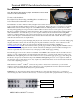
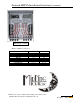
Positive Connections
Negative Connections
MNPV8-MC4 with MC4
®
Connectors
Installation
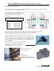
Note: The plastic dead front fits very tight. You must first remove the lid
in order to remove the deadfront.
To remove the deadfront:
Pry off the lid as shown using something like a screwdriver as a
lever. The dead front then lifts out easily.
The installation of a PV combiner is fairly straight forward. Select the location to install your combiner first.
Some systems have the PV modules located close to the inverters. If this is the case, you can elect to mount the
MNPV inside and run each PV string down to the MNPV inside the building. This is convenient for trouble
shooting and upgrading. For longer runs the combiner will be mounted outdoors on the pole for pole mounted
PV arrays or similar mounting for rack mounted arrays. The combiner can be mounted in the vertical position or
slanted backwards to accommodate up to a 3/12 roof pitch. All unused holes should be blocked using RTV
sealant or something similar in order to keep rain and insects out of the enclosure. Care must be taken to insure
that no water will get on terminal busbars or fuse holders when mounted less than vertical. Be sure to comply
with all local and national code requirements.
Wiring with connectors is pretty much plug and play at least as far as the solar panels are concerned. Simply plug
the plus and minus connectors from each string into the plus and minus connectors on the combiner. See the
example on the next page. There are various wiring diagrams and system examples available at
www.midnitesolar.com click on Documents at the top of the page for links to wiring diagrams in PDF as well as
links to AutoCad wiring diagrams and even solid models aimed at aiding the system installer and designer. As
such we request that they not be used for any other purpose. Well, maybe puppy training.
The following photos show the connections available on the MNPV8. Note that the center bottom knock out is
sized for a 1 1/4” conduit adapter. The left and right side each have a ½” knock out for either wire entry or for
MNSPD and other lightning arrestors. Follow directions above (seal with an appropriate goop) when using side
knockouts to keep water off internal components. MidNite SPD lightning arrestors do not require a locknut on
the outside in order to clear the lid, nor do they require any sealant. Delta arrestors are not UL listed and should
not be used as lightning protection.
With either the Solarlok
®
or MC4
®
connectors the positive connection is located near top cover and the
negative is located towards the back of the combiner. Use only compatible interconnect cables. The Solarlok
®
connectors may look identical but are keyed for plus and minus.
Caution! Do not disconnect any cables under load. Remove power at the disconnect prior to connecting or
disconnecting any cable connections. If necessary, cover the solar panels with opaque material to remove power.