
HV Disconnecting Combiner Manual


MNPVHV Disco Instructions (continued)
28 | P a g e 1 0 - 065- 1 R E V : J
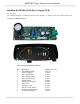
Installing the MNDiscoPSB Power Supply PCB: Continued
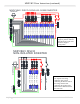
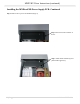
Step 7: Strip one end on the red and
white wires included in the kit ¼” and
connect them as shown with the red
wire on the left side of the terminal
block marked “PV+” and the white
wire on the right side marked “PV-“.
Route the wires downward under the
large switch.
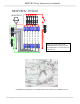
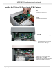
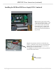
Step 7a: Strip the other end of the red and white wire
about ¼”. Install the red wire into the red terminal block.
Put the white wire along with the black wire from the
MNSPD into the ferrule and crimp.
If no MNSPD is installed the white wire may go directly
into the white terminal block.
Ferrule