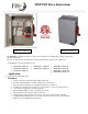
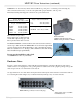
MNPVHV Disco Instructions MNPV8HV TYPE 4X MNPV6HV TYPE 4X The MNPVHV combiners are rated for outdoor use. Designed for combining high voltage strings using 10mm x 38mm fuses. The use of touch safe din rail mount fuses and fuse holders allows operation up to 600 Volts.
MNPVHV Disco Instructions (continued) IMPORTANT SAFETY INSTRUCTIONS SAVE THESE INSTRUCTIONS - These instructions contain important safety and operating instructions for the MidNite Solar MNPVHV Disconnecting solar combiner boxes. If you do not fully understand any of the concepts, terminology, or hazards outlined in these instructions, please refer installation to a qualified dealer, electrician or installer. These instructions are not meant to be a complete explanation of a renewable energy system.
MNPVHV Disco Instructions (continued) Table of Contents Introduction ............................................................................................................................................. 3 Installation ................................................................................................................................................ 3 Wire torque requirements.................................................................................................................
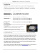
MNPVHV Disco Instructions (continued) Introduction The MNPVHV series of combiners are designed for indoor / outdoor use. Type 4X have been tested to be watertight to 2 meters underwater, so they are sure to be watertight above sea level. The MNPV4HV and MNPV6HV are basic disconnecting combiners while the MNPV8HV and MNPV16HV are reconfigurable to accommodate Non-Isolated inverters or to divide one combiner into two separate halves to power 2 inverters.
MNPVHV Disco Instructions (continued) Caution! Do not disconnect any cables under load. Remove power prior to connecting or disconnecting any cable connections. If necessary, cover the solar panels with opaque material to remove power. Extremely bad things Will happen if connections are opened under load. Torque –Fuseholder USM1 Fuse holder 15 in-lbs (1.7Nm) Torque – Terminal Bus Bar 10AWG 8AWG 6AWG 4AWG 2AWG – 1/0 20 in-lbs (2.3Nm) 25 in-lbs (2.8Nm) 35 in-lbs (4.0Nm) 45 in-lbs (5.1Nm) 50 in-lbs (5.
MNPVHV Disco Instructions (continued) Enclosure Notes Continued: Tighten hole plugs firmly on 4X units with MidNite Solar tool part number 5-151-1 (included). Tighten from the inside of the combiner to avoid twisting the gasket. Tighten from the inside of the combiner Hole plug parts placement on Type 4X Chassis Installing adapter fittings: When using reducing adapters, install the adapter and gasket through the front and the nut from inside the combiner.
MNPVHV Disco Instructions (continued) Reconfiguring MNPVHV Combiners: MNPVHV Combiners come complete with all the busbars and additional labels required to reconfigure to any of the three possible configurations, Non-Isolated, 2 Inverter and Parallel. All combiners are shipped from the factory setup as parallel. You will need: #2 Phillips screwdriver 5/16, 3/8 and 7/16 wrenches Slotted screwdriver Crimper for MNSPD ring lugs (If needed) First, the definition of the configurations. 1.
MNPVHV Disco Instructions (continued) Reconfiguring MNPVHV Combiners continued: MNPV16HV The following instructions assume starting from the default (parallel) configuration. If starting from another setup then either revert to the default (Parallel) configuration or follow the instructions for the desired configuration bearing in mind that the instructions may ask you to add/remove a busbar or label that has already been added/removed.
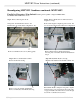
MNPVHV Disco Instructions (continued) Reconfiguring MNPVHV Combiners continued: MNPV16HV Parallel to 2 Inverters / Non-Isolated: Starting with a parallel configured MNPV16HV. The MNPV16HV TYPE 4X is shown. Step 1: Remove PV Negative block Step 2: Remove PV Positive Combined Out and Negative box lugs Change left “PV POSITIVE” label to “PV NEGATIVE” on Non-Isolated configuration only. Remove PV Negative Output lug and set aside. It is not used in the 2 Inverter/Non-Isolated configuration.
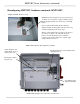
MNPVHV Disco Instructions (continued) Reconfiguring MNPVHV Combiners continued: MNPV16HV Step 5: Install PV Positive box lug Install PV Positive Output box lug on bottom position of switch. See torque chart on page 4. Finally, replace the PV Negative busbar removed in step 1 and install busbar.
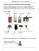
MNPVHV Disco Instructions (continued) Reconfiguring MNPVHV Combiners continued: MNPV8HV 9-458-2 STRAIN RELIEF 5-147-1 CONDUIT NUT 5-146-1 HOLE PLUG 5-149-1 WASHER 5-147-1 NUT 6-168-1 FERRULE 6-034-2 HEX HEAD SCREW 6-016-1 KEPNUT 9-377-1 RING LUG 6-166-1 FERRULE MNPV8HV Hardware Kit 11 | P a g e 10-065-1 REV:F
MNPVHV Disco Instructions (continued) Reconfiguring MNPVHV Combiners continued: MNPV8HV PV Negative busbar for Non-Isolated configuration These additional busbars supplied with the MNPV8HV Combiner are all that is needed to convert it to any of its configurations PV Positive busbar for 2 Inverter configuration Parallel to 2 Inverters: See page 6 for a definition of each configuration. Starting with a parallel configured MNPV8HV.
MNPVHV Disco Instructions (continued) Reconfiguring MNPVHV Combiners continued: MNPV8HV Step 4: Reinstall Positive block Step 5: Reinstall Negative block Install block. Refer to torque chart on page 4. Use screws removed in step 1 Install block. Refer to torque chart on page 4. Use screws removed in step 1 MNPV8HV 2 Inverter Reconfiguration checklist PV Positive Output busbar jumper removed (step 2). PV Negative busbar jumper removed (Step 1).
MNPVHV Disco Instructions (continued) Reconfiguring MNPVHV Combiners continued: MNPV8HV Parallel to Non-Isolated: Starting with a parallel configured MNPV8HV. The MNPV8HV TYPE 4X is shown, but the process is the same for the MNPV8HV TYPE 3R. Step 1: Remove Output blocks and Negative jumper busbar Step 2: Remove Positive Output busbar Replace only this nut at this time Remove Positive and Negative blocks and set aside. This is to provide access for the next steps.
MNPVHV Disco Instructions (continued) Reconfiguring MNPVHV Combiners continued: MNPV8HV Step 4: Reinstall Negative block Install Negative out block with screws removed in step 1. Tighten onto busbars. Refer to torque chart on page 4. Step 5: Reinstall block These terminal blocks are not used in this configuration. If desired you may remove them and use elsewhere, otherwise you may leave them installed here. Be sure to seal any holes left open.
MNPVHV Disco Instructions (continued) MNPV4HV and MNPV6HV Combiners MNPV4HV TYPE 3R Deluxe MNPV6HV TYPE 4X MNPV4HV TYPE 3R Basic, MNPV4HV TYPE 3R Deluxe and MNPV6HV TYPE 4X Combiners are shipped configured as 4 or 6 string combiners and are not field reconfigurable. MNPV4HV Disco 3R - Basic Disconnecting Combiner has 80 amp busbars, 100 amp switch and has two poles in series to make a 600V switch. Refer to MNPV6HV wiring diagram on page 22.
MNPVHV Disco Instructions (continued) MNPVHV8-DLTL and MNPVHV16-DLTL Combiners The MNPVHV8-DLTL and MNPVHV16-DLTL Combiners are available in NEMA 3R and NEMA 4X models. They are split into two sections each with separate positive and negative for each section. These combiners are fully compatible with the MidNite Solar Rapid Shutdown System. The MNPV8HV-DLTL allows you to take 4 strings in and combine them into 2 strings out. So String 1 and 2 go to channel A out and String 3 and 4 go to channel B.
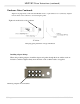
MNPVHV Disco Instructions (continued) Installing MNSPD: The MNPVHV Combiner comes with 1 MNSPD to protect against surges. A second MNSPD (sold separately) can be added to protect 2 inverter configurations. Refer to the wiring diagrams starting on page 17. MNSPD Surge Protector Device Remove the hole plug from the side of the combiner. Remove the nut from the MNSPD. Pull the wires through the side of the combiner and secure with the supplied nut.
MNPVHV Disco Instructions (continued) Ring lugs are included to allow easy installation of the MNSPD. If they are to be used, then you would need to strip the wire, push it into the barrel of the ring lug and crimp the barrel with an appropriate crimper. Make sure to pull on the wire after crimping to verify that the crimp is adequate. Black wire from MNSPD Red wire from MNSPD Green wire from MNSPD Connections for Non-Isolated.
MNPVHV Disco Instructions (continued) Wiring The MNPVHV Combiners can be configured to meet the combining and disconnecting needs of a wide array of solar system setups. All Combiners are shipped from the factory configured as parallel. Below are the various wiring diagrams. Reconfiguring the combiner is covered in detail starting page 6. PV MINUS Here the Combiner is set up as two separate eight string combiners.
MNPVHV Disco Instructions (continued) MNPV16HV DISCO- PARALLEL 50KW INVERTER MNSPD600 PV MINUS FUSES GROUND PV PLUS OUT UP TO 600 VOC UP TO 600 VOC UP TO 600 VOC UP TO 600 VOC UP TO 600 VOC UP TO 600 VOC UP TO 600 VOC _ _ _ _ _ _ _ _ + + + + + + + + UP TO 600 VOC UP TO 600 VOC UP TO 600 VOC UP TO 600 VOC UP TO 600 VOC UP TO 600 VOC UP TO 600 VOC UP TO 600 VOC UP TO 600 VOC PV MINUS OUT PV MINUS + + + + + + + + _ _ _ _ _ _ _ _ The parallel setup gives you a single 16 position comb
MNPVHV Disco Instructions (continued) MNPV8HV DISCO 2 INVERTERS PV PLUS PV PLUS UP TO 600 VOC UP TO 600 VOC UP TO 600 VOC UP TO 600 VOC UP TO 600 VOC UP TO 600 VOC UP TO 600 VOC PV MINUS GROUND UP TO 600 VOC MNSPD600 PV MINUS MNSPD600 This arrangement allows the 8 position combiner to act as two separate 4 position combiners that disconnect together. Note that the second MNSPD600 is sold separately.
MNPVHV Disco Instructions (continued) MNPV6HV DISCO MNSPD600 _ _ _ _ _ _ PV PLUS OUT UP TO 600 VOC UP TO 600 VOC UP TO 600 VOC UP TO 600 VOC UP TO 600 VOC UP TO 600 VOC PV MINUS OUT GROUND PV MINUS + + + + + + This is the typical wiring for the MNPV6HV Disconnecting Combiner. The MNPV4HV is wired the same but with 4 strings All Midnite Solar products are assembled under the watchful eye of Midnite the cat.
MNPVHV Disco Instructions (continued) Optional Accessories MNBirdhouse • Located at ground level, the Birdhouse provides a safe means to disconnect high voltage PV arrays from MidNite Disconnecting and Arc Fault combiners • Hard wired connection gives positive feedback that the Disconnect on the roof has actually been thrown.
MNPVHV Disco Instructions (continued) Installing the MNDiscoPSB Power Supply PCB: You will need: 3/16” Slotted screwdriver, #1 Phillips screwdriver, Wire strippers, ¼” nutdriver and a wire crimper to attach lugs. Included in the MNDiscoPSB Kit. Parts included with MNDiscoPSB kit.
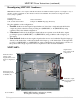
MNPVHV Disco Instructions (continued) Installing the MNDiscoPSB Power Supply PCB: Continued Step 1: Remove the top cover and deadfront (Page 3). Step 2: Remove plastic supports (2) by removing screws from the back side of the combiner. Set aside to reinstall later. Step 3: Place the Formex insulator as shown. Step 4: Install metal standoffs (2) and Reinstall plastic PCB supports removed in Step 1 (2).
MNPVHV Disco Instructions (continued) Installing the MNDiscoPSB Power Supply PCB: Continued Note: Circuit board is shown without non-removable clear cover. Step 5A: Set board in place as shown. Step 5B: Secure board with 6-32 screws (2). Loosen wire bundle from switch Trim wires to 5” and strip ¼” Step 6: Connect the two black wires to The left side of the terminal block marked “BK1” and “BK2”. Connect the two red wires to the right side of the terminal block marked “S1” and “S2”.
MNPVHV Disco Instructions (continued) Installing the MNDiscoPSB Power Supply PCB: Continued Step 7: Strip one end on the red and white wires included in the kit ¼” and connect them as shown with the red wire on the left side of the terminal block marked “PV+” and the white wire on the right side marked “PV-“. Route the wires downward under the large switch. Step 8: Installing the included MNSPD Surge protector with the MNDiscoPSB. First, select the mounting location for the MNSPD.
MNPVHV Disco Instructions (continued) Installing the MNDiscoPSB Power Supply PCB: Continued Step 9: Verify your work then replace deadfront and top cover. MNPVHV4 TYPE 3R Shown wired with MNDiscoPSB power supply board and MNSPD surge protector.
MNPVHV Disco Instructions (continued) MNPV8HVMCM300 Adaptor Kit The MNPV8HVMCM300 adaptor kit is available for the MNPV8HV to allow the use of larger output wires, up to 300 MCM. If required, new units ship with this kit installed. Positive Busbar Negative Busbar Box Lugs MNPV8HVMCM300 Adaptor Kit Penny shown for reference of scale Positive Output Lug Negative Output Lug Step 1: Install Box Lugs onto busbars as shown. Step 2: Remove white plastic cover from the negative output Busbar.
MNPVHV Disco Instructions (continued) Step 3: Remove red plastic cover from the Positive output terminal Busbar. Remove existing Positive output Busbar. Step 3A: Install Busbar and Lug assembly and tighten. Refer to the torque chart on page 4 Replace Red plastic cover. It may be necessary to loosen the Positive Output Terminal Busbar to remove / reinstall busbars. The MNPV8HV is now ready to accept up to 300 MCM output wires. MNPV8HVMCM300 Kit fully installed.
MNPVHV Disco Instructions (continued) MNPV4HV TYPE 3R, INCLUDED/REPLACEMENT PARTS: MIDNITE SOLAR PART NUMBER 1 EACH DEADFRONT 4 EACH LOCKNUT ½ INCH 4 EACH FUSES, 4 EACH STRAIN RELIEF 5-101-1 6-092-1 9-084-1 9-458-2 MNPV6HV TYPE 4X, INCLUDED/REPLACEMENT PARTS: MIDNITE SOLAR PART NUMBER 6 EACH BLACK TWO WIRE STRAIN RELIEFS, 10 EACH ½ INCH NUTS, SURGE PROTECTION DEVICE 6 EACH FUSES, DEADFRONT HOLE PLUG WASHER 9-458-2 5-147-1 MNSPD 600V 9-084-1 5-120-1 5-146-1 5-149-1 MNPV8HV TYPE 3R, INCLUDED/REPLACEME
MNPVHV Disco Instructions (continued) Appendix A MNPV4HV MNPV4HV Bottom and side knockout location and size No Scale 33 | P a g e 10-065-1 REV:F
MNPVHV Disco Instructions (continued) MNPV6HV MNPV6HV Bottom and side knockout location and size No Scale 34 | P a g e 10-065-1 REV:F
MNPVHV Disco Instructions (continued) MNPV8HV MNPV8HV Type 4X Bottom and side knockout location and size No Scale 35 | P a g e 10-065-1 REV:F
MNPVHV Disco Instructions (continued) MNPV8HV MNPV8HV Type 3R Bottom and side knockout location and size No Scale 36 | P a g e 10-065-1 REV:F
MNPVHV Disco Instructions (continued) MNPV16HV MNPV16HV Bottom and side knockout location and size No Scale 37 | P a g e 10-065-1 REV:F
MNPVHV Disco Instructions (continued) MIDNITE SOLAR INC. LIMITED WARRANTY MidNite Solar Power electronics, sheet metal enclosures and accessories MidNite Solar Inc. warrants to the original customer that its products shall be free from defects in materials and workmanship. This warranty will be valid for a period of five (5) years for all products except the MNKID Charge Controller which will be two (2) years.