
Installation Manual


MNPVHV Disco Instructions (continued)
27 | P a g e 1 0 - 065- 1 R E V : F
Installing the MNDiscoPSB Power Supply PCB: Continued
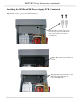
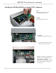
Step 5B:
Secure board with 6-32 screws (2).
Loosen wire bundle from switch
Trim wires to 5” and strip ¼”
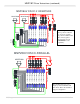
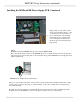
Step 6: Connect the two black wires to
The left side of the terminal block
marked “BK1” and “BK2”.
Connect the two red wires to the right
side of the terminal block marked
“S1” and “S2”.
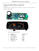
Note:
Circuit board is shown without
non-removable clear cover.
Step 5A:
Set board in place as shown.