
SOB Manual

MNSOB Shut Off Box Instructions (continued)
10 | P a g e 1 0 - 283- 1 R E V : P 5
Installing the MNDiscoPSB Power Supply PCB: Continued
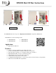
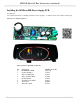
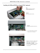
Step 7: Strip one end on the red and
white wires included in the kit ¼” and
connect them as shown with the red
wire on the left side of the terminal
block marked “PV+” and the white
wire on the right side marked “PV-“.
Route the wires downward under the
large switch.
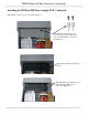
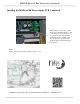
Step 8:
Verify your work, then replace deadfront and top cover.
All Midnite Solar products are assembled under the watchful eye of Midnite the cat.