
Schneider XW E-Panel Manual


XW E-Panel installation manual
8 | P a g e 10- 1 8 5 - 1 R E V : -
The DC-GFP device monitors current flowing between battery negative and earth ground and will
trip when more than ½ amp is present. There should be no current flowing in this circuit under
normal circumstances. In the event your DC-GFP trips, it is usually on a new installation. One of
two things is happening. 1: There is an actual ground fault in the wiring, or 2: there is an excess of
current flowing through the large 63 or 80 amp breaker. The first thing an installer usually suspects
in the case of this device tripping is that the device is faulty. Sorry, but this will not be the reason
for a DC-GFP tripping, so check your wiring! Refer to the wiring diagram in these instructions or
on the inside of the door. These wiring diagrams show a PV disconnect breaker connected directly
after the PV array + busbar and before the DC-GFP. It doesn’t matter which order these two devices
are connected. The DC-GFP can be connected to the Array plus output before the PV disconnect
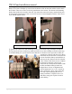
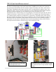
just as well. Make sure the polarity of all DC breakers are correct. The din rail mount breakers have
a + sign at the bottom terminal. Panel mount breakers have a “Line” marking on the top connection.
The + and Line connections need to be connected to the most positive point in the circuit. Since the
DC-GFP is acting as a switch and not as a breaker, the PV disconnect is the device that polarity
needs to be observed. It is much easier to wire the din rail mount devices as shown in the picture,
but the DC-GFP + connection is furthest away from the PV+ array. In the case of the panel mount
80 amp PV disconnect breaker and 80 amp DC-GFP, connect the PV+ array output to the top of the
PV disconnect breaker. The DC-GFP polarity will not be important. The polarity of the PV
disconnect breaker is important!
The output of the PV charge controller also requires over-current protection. Most installations will
use either a 63 amp din rail mount breaker or an 80 amp panel mount breaker. The + or “Line” side
of this breaker must be connected to the Battery+ busbar. Use a red 6AWG wire for the 63 amp
breaker and 4AWG wire for an 80 amp breaker. The charge controller output breaker must be sized
large enough for the expected output. You can always use a larger breaker and wire than the array
output though. The breaker is there to protect the wire, not the controller, so you can use a 63 amp
breaker even if the controller is not capable of outputting more than 30 amps.
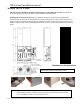
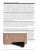
Solar Controller hook up: The E-Panel is set up to accept numerous controllers. These controllers
may be installed on either side of the enclosure using brackets like shown below.
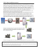
The bracket below is the standard bracket that comes with every E-Panel. If your controller must
mount to the opposite side, then order a MNCCB-Left. This bracket directly accepts the MidNite
Classic controller, OutBack MX60, FM60 and FM80. Some PWM controllers such as the Xantrex
C40/C60 and the
Morningstar Tristar 60
can also mount to this
bracket by adding an
additional mounting
hole. The Xantrex
MPPT controller does
not require a bracket. It
mounts to the two holes
marked with arrows.