
Schneider XW E-Panel Manual


XW E-Panel installation manual
9 | P a g e 10- 1 8 5 - 1 R E V : -
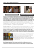
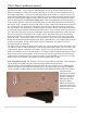
Wires pass through a 1” conduit knockout in the side
plate. Install a 1” Close nipple, three 1” locknuts and two
bushings to complete the wire passage. One of the
locknuts is placed between the two enclosures to act as a spacer. The picture to the right shows the
MidNite Classic installed. Note the two 80 amp panel mount breakers. The E-Panel can accept up to
three panel mount breakers on either side and up to seven din rail mount breakers. Din rail breakers
go up to 63 amps at the present. Panel mount breakers are available in 80 amps and even higher.
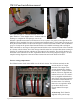
Most controllers are too large to allow panel mount breakers to be mounted in front of the controller
as is shown with the Classic here. Each charge controller must have a breaker/disconnect coming in
from the PV combiner and also a breaker on the output of the controller. The need for breakers on
both sides of the controller is an NEC requirement. Refer to the wiring diagram on page 6. A more
complete wiring diagram is at the end of these instructions and on the inside of the door.
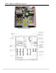
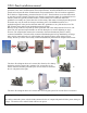
Inverter wiring compartment:
The E-Panel comes wired with 6AWG wire for all AC circuits. The left three terminals on the
inverter are the AC output
terminals. The output of the
inverter terminals are wired to
the E-Panel AC output terminal
busbars. Wires are supplied and
marked AC out. AC in 1 and AC
in 2 are supplied and marked as
such. These wires also connect to
the E-Panel terminal busbars of
the same name. Cut and strip
these wires as required to hook
up as shown. Refer to the
inverter manual for torque
values.
AC hook up: The E-Panel is
supplied with 2 pole 60 amp