
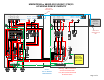
Wiring Diagram


OFFOFFOFFOFF
ONONONON
INVERTER 1 INPUT 2
L1
OUT
L1
IN 1
L2 OUT
L2 IN 1 L2 IN 2
L1
IN 2
NEUTRAL
NEUTRAL
OUT L1
GRID L1
GEN L1
NEUTRAL
NEUTRAL
INVERTER 1 INPUT 1
NORMAL
BYPASS
OFF
OFF
OFF OFF
ON ON
ON ON
ON
ON
OFF OFF
OFFOFF
ON ON
ONON
OFF OFF
OFFOFF
O
N
O
N
INVERTER 2 INPUT 1
INVERTER 2 INPUT 2
INVERTER 1
INVERTER 2
GRID L2
OUT L2
GEN L2
BATTERY
NEGATIVE
BATTERY
POSITIVE
BATTERY
NEGATIVE
BATTERY
POSITIVE
250
ON
OFF
250
ON
OFF
60
60
60
60
6060
60
60
L1
IN 2
L1
IN 1
L1
OUT
NEUTRAL
NEUTRAL
OUT L1
GRID L1
GEN L1
NEUTRAL
NEUTRAL
GRID L2
OUT L2
GEN L2
L2 OUT
L2 IN 1
L2 IN 2
OFFOFF
ON ON
INVERTER OUT
60
SYNCH
XANBUS
SYNCH
XANBUS
Grid InputAC out Gen Input
ON
ON
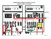
MNEDC100
MNEDC80
MNEDC100
MNEDC80
PV PLUS 1
PV PLUS 2
PAGE 2 of 2
ON
ON
Out to
Loads
In from
GRID
In from
Generator
Common Ground
for AC and DC
Common AC
Neutral for all AC
Cables to
Battery Bank
PV1 and PV2
Negative goes here
PV Positive
Array1
PV Positive
Array2
PV Ground
MNXWP5548 or 6848D-3CL150-REVC-7/06/15
WIRING DONE BY CUSTOMER
Warning. These Connections are
for interconnection only. Do not
feed AC IN OR OUT from these
Remove this
Neutral to Ground
bond if this system
is grid connected
PV PLUS 3
PV Positive
Array 3
PV 3 Negative
goes here
ON
ON
Battery
Plus
Battery
Plus
MNEDC100
MNEDC80