CD 50 Solid State Capacitor Discharge Stud Welding System Owner’s Manual • Installation • Operation • Maintenance
©2001 MIDWEST FASTENERS, INC., all rights reserved.
TABLE OF CONTENTS GENERAL Warranty ......................................................................................... 4 Safety Precautions .......................................................................... 5 INTRODUCTION What is Stud Welding ? ................................................................... 6 How Does CD Stud Welding Differ From ARC Stud Welding ? .... 6 CD 50 Overview ............................................................................
WARRANTY All parts used in the assembly of your MIDWEST FASTENERS Stud Welding System are fully guaranteed for Ninety (90) days from delivery date. In addition, the Welding Capacitors are fully guaranteed for a period of One Hundred and Twenty (120) days from delivery date. Under this warranty, MIDWEST FASTENERS reserves the right to repair or replace, at its option, defects in material or workmanship which occur during the warranty period.
SAFETY PRECAUTIONS • Comply with all electrical, fire and other applicable codes or ordinances in the installation and use of stud welding systems. • Remove all combustible or volatile materials from the weld area. Although weld splatter resulting from stud welding is normally minimal, proper precautions should be taken when welding near or through combustible materials to insure that sparks or weld material do not come in contact with combustible material.
WHAT IS STUD WELDING ? Stud welding is a welding process where a “stud” (or similar metal part) is instantaneously end-joined to a metal workpiece. This process involves the same basic principles and metallurgical aspects as any other welding process. The equipment required to stud weld is composed of a direct current power supply, a controller, a weld gun and cables to tie the system components together. In most systems the power supply and controller are combined into one unit called the “Welder.
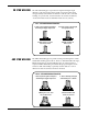
CD STUD WELDING The CD stud welding process produces weld power through a rapid discharge of the stored energy from a bank of capacitors. This stored energy is usually derived from a standard 115 volt AC source. CD stud welding, as a general rule, is used for studs 5/16" and less in diameter, (or where thin base metals or dissimilar metals are to be joined.) “CD” STUD WELDING PROCESS ARC STUD WELDING 1. Stud is placed against workpiece and weld gun trigger depressed 2.
OVERVIEW – CD 50 CAPACITOR DISCHARGE STUD WELDER The CD 50 is a capacitor discharge stud welder. The weld energy is stored in capacitors located inside the control unit. The amount of stored energy can be controlled by rotating the voltage control knob located on the front panel. CD weld studs, or pins, used with the CD 50 must have a specially designed projection at the weld end.
CD 50 INSTALLATION Follow the process below to properly install your CD 50 stud welder. CD 50 Cable Connections Controller CD CONTROL GUN Weld Gun Ground Cable GROUND CABLE NOTE: All cables should be laid out straight or in large loops. Poor welds may result if welding cables are closely coiled or stacked up. 1. Carefully remove the controller, cables and weld gun from the shipping packaging. 2.
CD 50 SETUP After installation, two setup phases must be completed before welding can begin. These phases are: • Weld Gun Setup, and • Controller Adjustment. WELD GUN SETUP Your weld gun setup will depend on your application and the particular stud to be welded. Setting up the gun consists of the following: 1. Locate the pins (or studs) that were shipped for your job and place a pin into the weld gun Collet with the “weld tip” protruding.
CD-2 WELD GUN SETUP INSULATION PINS . Adjustable Leg “B” Stop “B” Collet Foot Spark Shield (Optional) Weld Pin 1/8"- 3/16" Protrusion 1. Seat weld pin firmly against stop. 2. Loosen these adjustment screws. 3. Slide the Leg / Foot assembly until weld pin flange extends 1/8"- 3/16" beyond foot (or spark shield.) 4. Retighten adjustment screw. (Fig.1) CD-2 WELD GUN SETUP INSULATION PINS . Adjustable Leg / Foot “B” Stop Collet Protector (optional) “B” Collet (inside Protector) WITH .
CD-2 WELD GUN SETUP INSULATION PINS . Optional Weld Gun Setup for Insulation Pins Longer Than 4" (NOTE: shown with Internal Stop and Stop Adjuster used for long pins, rather than “B”-Stop.) WITH. Weld Pin INTERNAL STOP . 1/8 - 3/16" Protrusion 1. Seat weld pin firmly against internal stop. 2. Loosen these adjustment screws. 3. Slide the Leg / Foot assembly until weld pin flange extends 1/8"- 3/16" beyond foot (or spark shield.) 4. Retighten adjustment screw. (Fig.3) CD-2 WELD GUN SETUP WELD STUDS .
CD 50 SETUP CONTROLLER ADJUSTMENT & MAKING A TEST WELD After verifying that the welding system is installed and your weld gun is setup properly for your application, the final step is to adjust your stud welding controller to the proper settings. 1. (Before turning on power) turn the controller VOLTAGE selector switch to “MIN” (fully counterclockwise.) 2. Turn the controller ON/ OFF switch to “ON.” Verify by observing “POWER” lamp. 3.
5. Depress the weld gun trigger, wait momentarily, and then pull the gun straight back off the stud. 6. Test the weld integrity (see below.) WELD QUALITY Stud Welded Joint Quality GOOD HOT COLD Even weld fillet all around Excessive splatter and thin weld fillet Little or no weld fillet • A GOOD weld is determined by bending the stud back and forth. Failure should occur in the stud shank or workpiece, not in the weld. • HOT weld shows excessive splatter — adjust voltage downward (see 6. A. below).
PREVENTIVE MAINTENANCE Your MIDWEST FASTENERS welder is designed for long service with minimal care. Ordinary common sense maintenance will keep it operating efficiently. The following are a few tips on preventive maintenance. 1. Treat the cables with respect. Avoid sharp bends or kinks which may break the cables. DO NOT use the cables as a “ towline” to drag or lift the controller. Avoid damaging or straining the cables where they enter the gun or controller. 2.
TROUBLESHOOTING CHART PROBLEM 1. Welder does not turn on and will not weld. 2. Circuit Breaker trips or fuse blows each time the controller is turned on. 3. Circuit Breaker trips or fuse blows when weld is made. 4. Welder powers on, but does not operate. 16 POSSIBLE CAUSE CORRECTIVE ACTION A. Power cable connection at controller or 115 VAC outlet not complete. Inspect power cable connection. Repair if loose. B. Power cable/connector damaged. Check for continuity.
TROUBLESHOOTING CHART PROBLEM 4. Welder powers on, but does not operate. POSSIBLE CAUSE E. Shorted weld SCR. Unplug PC Board and check continuity between SCR heat sink and negative (–) buss bar. No reading should be observed. Replace SCR if continuity exists. A. Shorted charge SCR. Check continuity across SCR. No reading should be observed in either direction. Replace charge SCR if continuity exists. B. Faulty printed circuit board. Replace with new PC board if defective. C.
CD 50 STUD WELDING SYSTEM SPECIFICATIONS 9 " 15 ON " ER POW WE LD TAG VOL E X MA E MIN LTAG VO 8 " OFF 0 CD 5 N GU – OL NTR CO CD + BLE CA ND OU GR Weight .............................. 45 pounds Power Requirement .......... 115 VAC, 60 Hz, 20 Amp Pin/Stud Range ................ 14 ga. – 1/4" dia. Weldable Materials .......... Mild Steel, Stainless, & Aluminum Weld Mode....................... Contact Weld Rate.........................
CD 50 STUD WELDING SYSTEM EXPLODED VIEW DIAGRAM & PARTS LIST Item Qt’y. 1 2 3 4 5 6 7 8 9 1 2 10 11 3 4 12 5 6 7 43 42 8 9 10 11 12 41 13 40 14 39 15 38 16 37 17 18 36 19 35 20 34 33 21 32 22 31 23 30 24 25 26 27 28 29 13 14 15 16 17 18 19 20 21 22 23 24 25 26 27 28 29 30 31 32 33 34 35 36 37 38 39 40 41 42 43 44 © 2001 MIDWEST FASTENERS, INC.
CD 2 STUD WELDING GUN SPECIFICATIONS Weight .............................. 1-1/2 pounds (not including cables) Pin/Stud Range ................ 14 ga. – 1/ 4" dia. Weldable Materials .......... Mild Steel, Stainless, & Aluminum Material ............................ High strength, impact resistant, polycarbonate Cable Length .................... 35' 20 © 2001 MIDWEST FASTENERS, INC.
CD 2 STUD WELDING GUN EXPLODED VIEW DIAGRAM & PARTS LIST 3 4 5 6 7 8 9 10 11 12 13 14 33 15 34 16 35 17 18 36 32 19 31 20 30 29 28 21 22 23 24 25 26 2 27 1 Item Qt’y. 1 2 3 4 5 6 7 8 9 10 11 12 13 14 15 16 17 18 19 20 21 1 1 1 1 2 1 1 1 1 1 1 1 1 1 1 2 1 1 2 3 1 Part No.
115 / 220 VAC F1 22 CR R 220 VAC 110 VAC 110 VAC A – + 150 VAC 24 VAC A F2 5KΩ 25W IPL3 IPL10 IPL 8 IPL 5 CB VM IPL 7 25KΩ 50Ω 50W CR CR Cabinet Switch C1-5 IPL1 060-3081-01 Rev. 1 P.C. Board IPL 4 IPL9 IPL2 IPL6 + Gun Work (CD) Gun Trigger CD 50 STUD WELDING SYSTEM ELECTRICAL SCHEMATIC © 2001 MIDWEST FASTENERS, INC.
NOTES © 2001 MIDWEST FASTENERS, INC.