
Specs


Product and Cut-out Dimensions Page 3 of 4
CS 1011 Wok Burner CombiSet
CS
1011
Wok
Burner
CombiSet
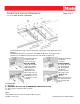
The illustration above re
p
resents the attachment of s
p
rin
g
cli
p
s 1 and su
pp
ort bars 2 for 3
Spring Clip installation
on wood or solid
surface countertop
Place the supplied
Spring Clip installation
on a
granite
countertop
Position and attach
ppgp
pp
appliances
An additional support bar is required for each additional appliance. The position for the
attachment of an additional support bar depends on the width of appliance B.
Place the supplied
spring clips 1 and the
support bars 2 at the
marked positions as
shown above, by
laying them on the
upper edge of the cut-
out and then securing
Position and attach
the spring clips 1 and
the supp
ort bars 2
with strong double-
sided tape 3
Coat the side and
lower edges of the
spring clips with
Location Codes
1 – Spring Clips
2 Support bars (Accessory item 27996029D CSZL 1500 (Includes cover 4))
them with the 1/8” x 1”
(3.5 x 25 mm) screws
(supplied)
pgp
silicone.
Fill the
space between
the support bars and
the countertop with
silicon
2 – Support bars (Accessory, item - 27996029D CSZL 1500 (Includes cover 4))
3 – Spac
e between support bar and countertop
4 – Cover
Notes
All installations must be done in accordance with local codes.
Drawing is not to scale Specification Sheets OJS
02212012