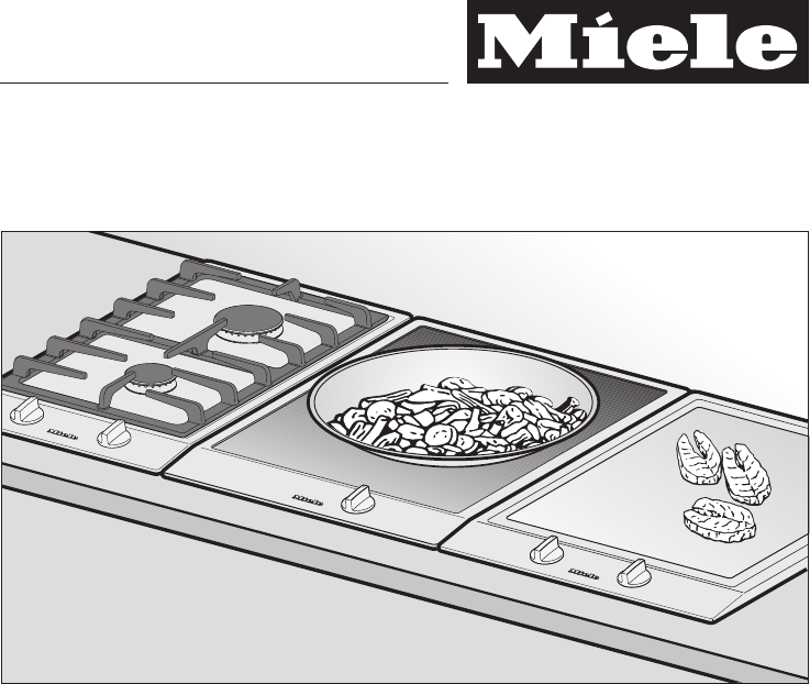
Operating and installation instructions Ceramic hobs with induction CS 1212 CS 1221 CS 1234 To avoid the risk of accidents or damage to the appliance, it is essential to read these instructions before it is installed and used for the first time. en - GB M.-Nr.
Contents Guide to the appliance . . . . . . . . . . . . . . . . . . . . . . . . . . . . . . . . . . . . . . . . . . . . . 4 CS 1212 . . . . . . . . . . . . . . . . . . . . . . . . . . . . . . . . . . . . . . . . . . . . . . . . . . . . . . . . . . 4 CS 1221 . . . . . . . . . . . . . . . . . . . . . . . . . . . . . . . . . . . . . . . . . . . . . . . . . . . . . . . . . . 5 CS 1234 . . . . . . . . . . . . . . . . . . . . . . . . . . . . . . . . . . . . . . . . . . . . . . . . . . . . . . . . . . 6 Display .
Contents Safety instructions for installation . . . . . . . . . . . . . . . . . . . . . . . . . . . . . . . . . . . 35 Appliance and building-in dimensions . . . . . . . . . . . . . . . . . . . . . . . . . . . . . . . 39 CS 1212 . . . . . . . . . . . . . . . . . . . . . . . . . . . . . . . . . . . . . . . . . . . . . . . . . . . . . . . . . 39 CS 1221 . . . . . . . . . . . . . . . . . . . . . . . . . . . . . . . . . . . . . . . . . . . . . . . . . . . . . . . . . 40 CS 1234 . . . . . . . . . . . . . . . . .
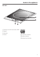
Guide to the appliance CS 1212 a Cooking zone with twin booster (BI/II) Cooking zone controls: b Cooking zone with single booster (Bl) f Rear c Display g Front d Cooking zone symbols e Indicators Indicators l In-operation indicator m Booster indicator n Residual heat indicator 4
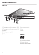
Guide to the appliance CS 1221 a Cooking zone with twin booster (BI/II) Indicators b Display c Indicators d Control l In-operation indicator m Booster indicator n Residual heat indicator 5
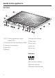
Guide to the appliance CS 1234 abd Cooking zones with single booster (BI) c Cooking zone with twin booster (BI/II) e Cooking zone symbols f Indicators Cooking zone controls: g Rear right h Front right i Rear left j Front left k Display Indicators l In-operation indicator m Booster indicator n Residual heat indicator 6
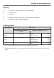
Guide to the appliance Display ß = No pan on cooking zone or pan unsuitable A = Auto heat-up I = Booster I II = Booster II (only for cooking zones with twin boosters) L = Safety lock (see "Safety features") Cooking zones Cooking zone CS 1212 minimum to maximum C in cm* Front Rear Rating in watts for 230 V** 10 - 16 normal: with booster: 1400 1800 16 - 23 normal: with Booster I: with Booster II: 2300 3000 3700 Total: 3700 * Pans of any diameter within the given range may be used.
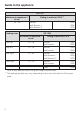
Guide to the appliance CS 1221 minimum to maximum C in cm* 18 - 30 Rating in watts for 230 V** normal: with Booster I: with Booster II: Cooking zone 2400 3000 3700 CS 1234 minimum to maximum C in cm* Rating in watts for 230 V** Front left 14 - 19 normal: with booster: 1850 2900 Rear left 14 - 19 normal: with booster: 1850 2900 Rear right 16 - 23 normal: with Booster I: with Booster II: 2300 3000 3700 Front right 10 - 16 normal: with booster: 1400 1800 Total: 7400 * Pans of any diamet
Warning and Safety instructions Correct application This appliance complies with current safety requirements. Inappropriate use can, however, lead to personal injury and damage to property. To avoid the risk of accidents and damage to the appliance, please read these instructions carefully before installation and before using it for the first time. They contain important notes on installation, safety, use and maintenance.
Warning and Safety instructions Safety with children ~ Activate the safety lock to ensure that children cannot switch on the appliance inadvertently. ~ This appliance is not a toy! To avoid the risk of injury, keep children away from it all times, and do not let them play with it or use the controls. They will not understand the potential dangers posed by it. They should be supervised whenever you are working in the kitchen.
Warning and Safety instructions Technical safety ~ Before installation, check the appliance for visible signs of damage. Do not use a damaged appliance. It could be dangerous. ~ The electrical safety of this appliance can only be guaranteed when continuity is complete between it and an effective earthing system which complies with local and national safety regulations.
Warning and Safety instructions ~ While the appliance is under guarantee, repairs should only be undertaken by a service technician authorised by Miele. Otherwise the guarantee is invalidated. ~ Faulty components must only be replaced by genuine Miele original spare parts. The manufacturer can only guarantee the safety of the appliance when Miele replacement parts are used.
Warning and Safety instructions Correct use ~ For people fitted with a heart pacemaker: Please note that the area immediately surrounding the hob is electromagnetically charged. It is unlikely to affect a pacemaker. If in any doubt, consult the manufacturer of the pacemaker or your doctor. ~ To prevent damage to items which are susceptible to magnetic fields, e.g. credit cards, diskettes, pocket calculators etc, do not leave them in the immediate vicinity of the hob.
Warning and Safety instructions ~ Do not use plastic or aluminium foil containers These melt at high temperatures and could catch fire. ~ Do not heat up unopened tins of food on the hob, as pressure will build up in the tin, causing it to explode. This could result in injury and scalding or damage. ~ Do not use pots and pans on the ceramic hob with bases with pronounced edges or ridges, e.g. cast iron pans. These could scratch or scour the hob surface permanently.
Warning and Safety instructions ~ Spray canisters, aerosols and other inflammable substances should not be stored in a drawer under the hob. Cutlery inserts must be heat-resistant. ~ This appliance must not be set up or ~ Metal utensils stored in a drawer under the hob can become hot if the induction hob is used intensively for a long time. Miele cannot be held liable for damage caused by non-compliance with these Warning and Safety instructions. operated in the open air.
Caring for the environment Disposal of the packing material The transport and protective packing has been selected from materials which are environmentally friendly for disposal, and should be recycled. Ensure that any plastic wrappings, bags, etc. are disposed of safely and kept out of the reach of babies and young children. Danger of suffocation.
Before using for the first time Please stick the extra data plate for the appliance supplied with this documentation in the space provided in the "After sales service, data plate" section of this booklet. Cleaning for the first time ^ Remove any protective wrapping and adhesive labels. ^ Before using for the first time, clean the appliance with a damp cloth only and then wipe dry. Do not use washing up liquid to clean the ceramic surface as it can leave a blue sheen which may be difficult to remove.
Induction The induction principle An induction coil is located under each cooking zone. When a cooking zone is switched on, this coil creates a magnetic field which impacts directly on the base of the pan and heats it up. The cooking zone itself is heated up indirectly by the heat given off by the pan. An induction cooking zone only works when a ferromagnetic pan is placed on it (see "Pans"). Induction automatically recognises the size of the pan, i.e.
Induction Noises When using an induction cooking zone, the following noises can occur in the pan, depending on what it is made of and how it has been constructed. – On the higher power settings, it might buzz. This will decrease or cease altogether when the power setting is reduced. The appliance has a cooling fan to help extend the life of the electronics. When the hob is being used intensively, this will come on and you will hear a whirring sound.
Induction Pans Suitable pans include: – stainless steel pans with a magnetic base – enamelled steel pans – cast iron pans Unsuitable pans: – stainless steel pans without a magnetic base – aluminium and copper pans – glass, ceramic or earthenware pots and pans To test whether a pot or pan is suitable for use on an induction hob, hold a magnet to the base of the pan. If the magnet sticks, the pan is suitable.
Operation Switching on and off Residual heat indicator The residual heat indicator remains on until the induction hob is cool enough to touch. Do not touch or place any heat sensitive objects on the hob while the residual heat display is still on. Danger of burning and fire. Each cooking zone is switched on by turning the control clockwise a to the power setting required, and is switched off by turning the control anticlockwise b to "0". Do not turn the control to "0" by turning it past BI or BI/II.
Operation Settings Cooking process Keeping warm Melting butter Dissolving gelatine Settings* ( 1-2 Making milk puddings 2 Warming small quantities of liquid Cooking rice Defrosting frozen vegetables Cooking pulses 3 Warming liquid and semi-solid foods Making omelettes and lightly frying eggs Steaming fruit Cooking dumplings 4 Steaming vegetables, fish Defrosting and reheating frozen food 5 Bringing large quantities of food to the boil, e.g. casseroles Thickening custard and sauces, e.g.
Operation Auto heat-up Activating Auto heat-up Continued cooking setting Heat-up time in minutes and seconds (approx.) ^ Turn the control anticlockwise as far as it will go and hold in that position until A appears in the display. 1 0 : 15 2 0 : 15 3 0 : 25 4 0 : 50 If you hold the control for too long, L will appear in the display which means that the lock has been activated (see "Safety features Safety lock").
Operation Booster function The cooking zones are equipped with Single (l) or Twin Boosters (I/II) (see "Guide to the appliance"). When activated, the power is boosted so that large quantities can be heated quickly, e.g. boiling water for cooking pasta. When Booster l or Booster ll is activated, the cooking zones will operate with extra power for 10 minutes. The booster function cannot be used with two cooking zones at the same time.
Operation To activate Booster l ^ Turn the control past power setting 9 to BI or BI/II, and then back to 9. I will appear in the display for the cooking zone and the B booster indicator will light up. To activate Booster II ^ Turn the control past power setting 9 to BI/II, and then back to 9. I will appear in the display for the cooking zone and the B booster indicator will light up. ^ Turn the control past power setting 9 to BI/II, and then back to 9 once more.
Operation Keeping warm Useful tips Each cooking zone has a keeping warm function. Only use pans for keeping food warm. Cover the pan with a lid. If the keeping warm function has been activated, the cooking zone will switch off automatically after a maximum of 2 hours. You do not have to stir food while it is being kept warm. This function is for keeping food that has just been cooked warm, i.e. food that is still hot. It is not for reheating food that has gone cold.
Tips on saving energy – Use a pan lid whenever possible to minimise heat loss. uncovered covered – Select a smaller pan when cooking small quantities. A smaller pan uses less energy than a larger pan with very little in it. – Cook with as little water as possible. – Once food has come to the boil or the pan is hot for frying, reduce the heat to a lower setting. – Cooking times are greatly reduced when using a pressure cooker.
Safety features Safety lock Safety switch-off Keep children away from the hob for their own safety. Your appliance is equipped with a safety lock to prevent the hob and cooking zones being switched on. Your hob is fitted with a safety switch-off feature in case you forget to switch it off yourself. The safety lock can only be activated when the cooking zones are switched off. Hobs with 2 cooking zones: The control on the right is used to activate and deactivate the lock.
Safety features Overheating protection All the induction coils and the cooling element for the electronics are fitted with an overheating protection mechanism. To prevent the induction coils and cooling element from overheating, the overheating protection mechanism works on the affected cooking zone or on the entire hob in the following ways: – If the booster function is being used, this will be deactivated.
Cleaning and care Miele offer a range of branded cleaning and conditioning agents for your hob. See "Optional accessories". ,Under no circumstances use a steam cleaning appliance to clean this appliance. The steam could reach the electrical components and cause a short circuit. The appliance should be cleaned after each use. Let it cool down to room temperature. To avoid water marks and limescale deposits use a soft cloth to dry surfaces that have been cleaned with water.
Cleaning and care Ceramic surfaces Stainless steel Wipe all coarse soiling off using a damp cloth. Stubborn soiling may need to be removed with a shielded scraper blade. The ceramic and stainless steel hob cleaner is suitable for cleaning stainless steel surfaces (see "Optional accessories"). To help prevent resoiling, we recommend a stainless steel conditioner (see "Accessories"). Apply sparingly with a soft cloth.
Problem solving guide ,Installation work and repairs to electrical appliances must only be carried out by a suitably qualified and competent person in strict accordance with current local and national safety regulations (BS 7671 in the UK). Repairs and other work by unqualified persons could be dangerous. The manufacturer cannot be held liable for unauthorised work. What to do if ... ... the cooking zones do not heat up. Check whether the mains fuse has tripped. If it has, reset the trip switch.
Problem solving guide ... after the cooking zone has been switched on for a few seconds L appears in the display. ... the food in the pan hardly heats up or does not heat up at all when the Auto heat-up function is switched on. The safety lock has been activated (see "Safety lock"). This could be because: ... H appears in one of the cooking zone displays. – the pan is not conducting heat properly. The overheating protection mechanism has been triggered (see "Overheating protection").
Optional accessories Miele branded cleaning and conditioning products are available for your appliance. These can be ordered via the internet at www.miele-shop.com or from Miele (see back cover for contact details). Ceramic and stainless steel hob cleaner 250 ml Removes heavy soiling, limescale deposits and aluminium residues Stainless steel conditioning agent 250 ml Removes water marks, flecks and finger prints. Helps keep the appliance looking good for longer.
Safety instructions for installation Fit the wall units and extractor hood before fitting the appliance to avoid damaging the surface. ~ The veneer or laminate coatings of worktops (or adjacent kitchen units) must be treated with 100 °C heat-resistant adhesive which will not dissolve or distort. Any backmoulds must be of heat-resistant material. ~ This appliance must not be installed over a dishwasher, washing machine, tumble dryer, refrigerator or freezer.
Safety instructions for installation Safety distance above the appliance A minimum safety distance must be maintained between the appliance and the cooker hood above it. See the cooker hood manufacturer's operating and installation instructions for details. If the manufacturer's instructions are not available for the cooker hood, a minimum safety distance of at least 760 mm must be maintained. For any flammable objects, e.g. utensil rails, wall units etc.
Safety instructions for installation Safety distances to the sides of the appliance Ideally the appliance should be installed with plenty of space on either side. There may be a wall at the rear and a tall unit or wall at one side. On the other side, however, no unit or divider should stand higher than the built-in appliance (see illustrations).
Safety instructions for installation Safety distance when installing the appliance near a wall with additional niche cladding A minimum safety distance must be maintained between the worktop cut-out and any niche cladding to protect it from heat damage. If the niche cladding is made from a combustible material (e. g. wood) a minimum safety distance e of 50 mm must be maintained between the cut-out and the cladding. If the niche cladding is made from a non-combustible material (e. g.
Appliance and building-in dimensions CS 1212 a Spring clamps b Front c Casing depth d Casing depth including mains connection box with mains connection cable, L = 1,440 mm 39
Appliance and building-in dimensions CS 1221 a Spring clamps b Front c Casing depth d Casing depth including mains connection box with mains connection cable, L = 1,440 mm 40
Appliance and building-in dimensions CS 1234 a Spring clamps b Front c Casingdepth d Casing depth including mains connection box with mains connection cable, L = 2,000 mm 41
Preparing the worktop ^ Make the worktop cut-out for one or more appliances as applicable. Remember to maintain a minimum safety distance from the back wall, as well as from any tall unit or side wall to the right or left of the appliance. See "Safety instructions for installation". ^ Seal the cut surfaces with a suitable heat-resistant sealant to avoid swelling caused by moisture. Make sure that sealant does not come in contact with the top of the worktop.
Installation of several appliances When installing two or more appliances next to each other a spacer bar b must be used between each one. See "Fixing the spring clamps and spacer bars". Worktop cut-out - two appliances Worktop cut-out - three appliances To calculate the cut-out width (D) required: Add up the widths of each appliance (e.g. width A + B + C etc.) and subtract 16 mm from this figure (i.e. 8 mm is taken off either end of the appliance run).
Installation of several appliances a Spring clamps b Spacer bars c Gap between spacer bar and worktop d Sealing strip The illustration shows a worktop cut-out with spring clamps a and spacer bars b for 3 appliances. An additional spacer bar is required for each additional appliance. The position for securing each additional spacer bar will depend on the width of appliance B (288 mm / 380 mm / 576 mm).
Fixing the spring clamps and spacer bars Wooden worktops ^ Position the spring clamps supplied a and spacer bars b on the top edge of the cut-out in the positions marked. ^ Secure the spring clamps and spacer bars with the 3.5 x 25 mm screws supplied.
Fixing the spring clamps and spacer bars Granite and marble worktops The screws are not required for granite or marble worktops. ^ Apply silcone to the side edges and the lower edges of the spring clamps a and spacer bars b. ^ Position and secure the spring clamps a and spacer bars b using strong, double-sided adhesive tape c. 46 ^ Then fill gap e between the spacer bars and the worktop with silicone from the tube supplied.
Installing the appliance(s) ^ Feed the connection cable down through the cut-out. ^ Starting at the front, position the next appliance in the worktop cut-out. ^ Starting at the front, position the appliance in the worktop cut-out. ^ Connect each appliance to the mains (see "Electrical connection"). ^ Using both hands, press down evenly on the sides of the appliance until it clicks into position. When doing this make sure that the seal under the appliance sits flush with the worktop on all sides.
General installation tips Tiled worktop Do not use any sealant unless expressly instructed to do so. The sealing strip under the edge of the top part of the appliance provides a sufficient seal for the worktop. Do not use sealant between the frame of the top part of the appliance and the worktop. This could cause difficulties if the appliance ever needs to be taken out for servicing and possibly result in damage to the frame or the worktop.
Electrical connection All electrical work should be carried out by a suitably qualified and competent person in strict accordance with current local and national safety regulations (BS 7671 in the UK). Connection should be made via a fused plug and switched socket or a double pole fused spur connection unit, or a suitable isolator (as appropriate) which complies with national and local safety regulations and the on/off switch should be easily accessible after the appliance has been built in.
Electrical connection Important The electrical safety of this appliance can only be guaranteed when continuity is complete between the appliance and an effective earthing system, which complies with local and national regulations. It is most important that this basic safety requirement is present and tested regularly and if there is any doubt the electrical wiring in the home should be inspected by a qualified electrician.
Electrical connection Wiring diagram CS 1234 a b c L1 L2 d L3 - N 200-240 V~ 200 - 240 V~ 200 - 240 V~ a b c L1 L2 d - N (L3) 200 - 240 V~ 200 - 240 V~ a b c L1 d - N (L2) 200 - 240 V~ N.B. This appliance is supplied single phase only in the U.K.
After sales service, data plate In the event of any faults which you cannot remedy yourself, or if the appliance is under guarantee, please contact: – Your Miele dealer, or – the Miele Customer Contact Centre (see back cover for address). Please note that telephone calls may be monitored and recorded to improve our service. When contacting Miele, please quote the model and serial number of your appliance which are given on the data plate. N.B.
Alteration rights reserved/ 4310 M.-Nr.