Operating and Installation Instructions Gas Combiset CS 1028 ® To prevent accidents and appliance damage, read these instructions before installation or use. ® en - US, CA M.-Nr.
WARNING: If the information in this manual is not followed exactly, a fire or explosion may result causing property damage, personal injury or death. – Do not store or use gasoline or other flammable vapors and liquids in the vicinity of this or any other appliance. – WHAT TO DO IF YOU SMELL GAS ß Do not try to light any appliance. ß Do not touch any electrical switch. ß Do not use any phone in your building. ß Immediately call your gas supplier from a neighbor’s phone.
Contents IMPORTANT SAFETY INSTRUCTIONS. . . . . . . . . . . . . . . . . . . . . . . . . . . . . . . . . 4 Guide to the combiset . . . . . . . . . . . . . . . . . . . . . . . . . . . . . . . . . . . . . . . . . . . . . . 9 Burner . . . . . . . . . . . . . . . . . . . . . . . . . . . . . . . . . . . . . . . . . . . . . . . . . . . . . . . . . . 10 Before using the combiset . . . . . . . . . . . . . . . . . . . . . . . . . . . . . . . . . . . . . . . . . 11 Operation . . . . . . . . . . . . . . . . . . . . . .
IMPORTANT SAFETY INSTRUCTIONS Children WARNING- When using your gas appliance follow basic precautions, including the following: This gas combiset conforms to all uniform safety codes and regulations. Read all instructions before installation or use to prevent injury and appliance damage. Keep these operating instructions in a safe place and pass them on to any future user.
IMPORTANT SAFETY INSTRUCTIONS Technical safety ~ Installation, repair and maintenance work should be performed by a Miele authorized service technician. Work by unqualified persons could be dangerous and may void the warranty. ~ Before installing the combiset, check for externally visible damage. Do not operate a damaged appliance. A damaged gas combiset is a hazard.
IMPORTANT SAFETY INSTRUCTIONS ~ Before servicing, turn off the gas valve and disconnect the power supply by either removing the fuse, unplugging the unit or manually “tripping” the circuit breaker. ~ This equipment has not been designed for maritime use or for use in mobile installations such as aircraft or recreational vehicles. However, under certain circumstances it may be possible for installation in these applications.
IMPORTANT SAFETY INSTRUCTIONS ~ Do not use pans that extend past the burner grate. Using larger pans may cause the flames to spread out and damage the surrounding countertop or other countertop appliances. ~ For safety and stability, do not use pans with a bottom diameter smaller than the burner grate. ~ Only certain types of glass, ceramic or other glazed cookware are suitable for use on a combiset without breaking due to the sudden temperature change. ~ Do not use containers made of plastic or aluminum.
IMPORTANT SAFETY INSTRUCTIONS ~ Make certain that the power cords of small appliances do not come in contact with the appliance. The insulation of the cable could become damaged. Danger of electric shock! ~ In the event of damage or defect, turn off the appliance immediately. Turn off the gas shut off valve and disconnect completely from the electrical supply. Contact the Miele Technical Service Department. Do not use the appliance until it has been repaired.
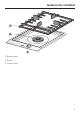
Guide to the combiset a Burner grate b Burner c Control knob 9
Guide to the combiset Burner d Burner cap e Burner head f Cover plate g Ignitor h Ignition safety control (Thermocouple) i Burner base 10
Before using the combiset Cleaning the combiset Before using for the first time clean the appliance as follows: ^ Remove any protective foil. ^ Wash the removable parts of the gas burner in a mild solution of warm water and liquid dish soap. Metal components have a protective coating which may give off a slight odor the first time your new appliance is heated. The harmless odor will dissipate after a short time and does not indicate a faulty connection or appliance defect.
Operation Turning on and off / Regulating Turning on The control knob is used to turn on the burner and to regulate the strength of the flame. ß The gas supply is turned off * Ignition setting & Highest flame / Lowest flame The knob must only be turned left to turn the appliance on and right to turn it off. If the knob is : - turned on without pressing it down first, - turned clockwise to turn on, or - turned counterclockwise to turn the combiset off, parts of the combiset might get damaged.
Operation Adjusting the flame The burner can be variably adjusted between the lowest and highest flame by turning the control knob. Using the cooktop during a power failure If there is an interruption to the electrical supply, the gas can be ignited using a match. ^ Press the control knob down and turn it counterclockwise to the ignition position. Since the outer portion of the flame is much hotter than the center, the flame should be set so that its tips do not spread beyond the sides of the pan.
Pans Pan size Suitable pans – Set the combiset to a high flame when using a large diameter pan and low flame when using a small diameter pan. Unlike pans used on an electric combiset, the bases do not need to be even for good results. – Generally, wide / shallow pans will heat faster and cook more evenly than narrow / tall ones. – Using oversized pans may cause the flames to spread out and damage the surrounding countertop or other countertop appliances.
Safety features Ignition Safety Control This gas combiset incorporates an Ignition Safety Control which stops the supply of gas if the flame goes out. ^ To reignite the burner, turn the control knob clockwise to “ß”, then turn on the burner as usual. This safety feature is not operated by electricity, it will be active even if the appliance is in use during a power failure.
Cleaning and care Combiset Never use a steam cleaner to clean this combiset. Pressurized steam could cause permanent damage to the surface and to components for which the manufacturer cannot accept responsibility. Do not use any sharp or pointed objects which could damage the seal between the frame and the countertop. Never use scouring agents, pads, abrasive cleaning agents, or strong cleaners, e.g. oven sprays, stain or rust removers, these could damage the surface of the appliance.
Cleaning and care Burner Reassembling the burner Do not clean any parts of the burner in a dishwasher. The burner can be dismantled and cleaned when cool. ^ Remove the burner parts and wash them in a solution of warm water and liquid dish soap. Dry them thoroughly. Make sure that the flame holes are clean and completely dry. ^ Wipe the burner base clean with a damp cloth and then dry. Gently wipe the ignitor and ignition safety control with a slightly damp cloth, and then wipe dry.
Frequently asked questions ,Repairs should only be carries out by an authorized technician in accordance with local and national safety regulations. Unauthorized repairs could cause injury or appliance damage. The manufacturer cannot be held responsible for unauthorized work. The burner does not ignite after several attempts. Possible fault Solution The burner is not assembled correctly. See "Cleaning and Care Reassembling the burner". The gas supply is not turned on. Turn on the gas supply.
Technical Service In the event of a fault which you cannot easily fix yourself, please contact the Miele Technical Service Department at the address on the back of this booklet. When contacting Technical Service please quote the serial number and model of the appliance. Adhere rating label sticker supplied with the appliance below.
Technical Service MieleCare (USA only) MieleCare, our Extended Service Contract program; gives you the assurance of knowing that your appliance investment is covered by 5 years of worry free ownership. MieleCare is the only Extended Service Contract in the industry that guarantees repairs by a Miele Authorized Service Provider using genuine Miele parts. Only genuine Miele parts installed by factory trained professionals can guarantee the safety, reliability and longevity of your Miele appliance.
Installation Instructions IMPORTANT: SAVE FOR THE LOCAL ELECTRICAL INSPECTOR'S USE To prevent accidents and appliance damage read these instructions before installation or use.
IMPORTANT SAFETY INSTRUCTIONS Installation The minimum distances given in these Installation instructions are to combustible surfaces, and must be observed to ensure safe operation. Failure to do so increases the risk of fire. The cabinetry and venting hood should be installed first to prevent damage to the combiset. ~ Deep fat fryers must not be installed directly next to gas combisets. Gas flames can ignite splattering oil.
IMPORTANT SAFETY INSTRUCTIONS Safety distances above the appliance The minimum safety distance given by the hood manufacturer must be maintained between the combiset and the hood above it. See the installation instructions of the hood for these safety measurements. If the hood manufacturers instructions are not available or if flammable objects are installed over the combiset (e.g. cabinets, utensil rail, etc.), a minimum safety distance of 30" (760 mm) must be maintained.
IMPORTANT SAFETY INSTRUCTIONS Safety distances to the sides of the appliance The appliance should only be installed as shown in the illustrations, while maintaining the required safety distances shown. Do not install the appliance between two tall cabinets, this is a fire hazard. A distance of at least 2" (50 mm) must be kept between the countertop cut-out and the rear wall because of the high temperatures radiated.
Installation Safety distance from the wall covering If a wall covering is installed, a minimum safety distance must be maintained between the countertop cut-out and the covering, since high temperatures can damage these materials. If the covering is made of a combustible material (such as wood), the distance between the countertop cut-out and the wall covering must be a minimum of 2" (50 mm).
Installation Installation dimensions a Spring clips b Appliance front c Installation height d Power supply box with connection cable, L = 78 3/4" (2000 mm) e Gas fitting f Rating label 26
Installation Cut out ^ Make the countertop cut-out for one or more appliances as applicable. Remember to maintain a minimum safety distance from the back wall, as well as from any tall unit or side wall to the right or left of the hob. See "IMPORTANT SAFETY INSTRUCTIONS". If during installation the seal around the frame does not sit flush with the countertop in the corners, the corner radius, maximum 3/16" (4 mm), can be carefully filed down to fit.
Installation Installation of multiple appliances When installing more than one combiset appliance, a support bar b must be installed between the appliances. Countertop cut-out two appliances Countertop cut-out three appliances For the installation of two appliances the width of the countertop cut-out D is the sum of A and C. For the installation of three appliances the width of the countertop cut-out D is the sum of A and B and C.
Installation Sample calculations for a countertop cut-out for three appliances A appliance width minus 5/16" (8 mm) B appliance width C appliance width minus 5/16" (8 mm) D Countertop cut-out 11" (280 mm) 11 5/16" (288 mm) 11" (280 mm) 33 3/8" (848 mm) 11" (280 mm) 15" (380 mm) 14 5/8" (372 mm) 40 5/8" (1032 mm) 11" (280 mm) 22 11/16" (576 mm) 22 3/8" (568 mm) 56 1/16" (1424 mm) 11" (280 mm) 37" (940 mm) 14 5/8" (372 mm) 44 1/4" (1124 mm) 14 5/8" (372 mm) 22 11/16" (576 mm) 22 3/8' (568
Installation a Spring clips b Support bars c Space between support bar and countertop d Sealing strip The illustration represents the attachment of spring clips a and support bars b for 3 appliances. An additional support bar is required for each additional appliance. The position for attachment of an additional support bar depends on the width of appliance B.
Installation Attach the spring clips and support bars Wood or solid surface countertops ^ Place the supplied spring clips a and the support bars b at the marked positions as shown above, by laying them on the upper edge of the cut-out and then securing them with the 1/8" x 1" (3.5 x 25 mm) screws (supplied).
Installation Granite countertop The screws are not needed for granite countertops. 3/16" 1"-1 (25-30 c mm) ^ Coat the edges of the spring clips a, a ^ and the space e between the support bars b and the countertop with silicone (supplied). ^ Position and attach the spring clips a and support bars b with strong, double-sided tape c.
Installation Installing the appliance / appliances ^ Place the front edge of the next appliance into the cut-out. ^ Feed the power cord down through the cut-out. ^ Connect the appliance / appliances to the main power supply (see "Electrical connection"). ^ Place the front edge of the appliance into the cut-out. ^ With a hand on each side of the appliance press down evenly on the edges until it clicks into position.
Installation Sealing Tiled surfaces The appliance must not be permanently sealed into the countertop when installed. The sealing strip under the edge of the appliance provides a sufficient seal for the countertop. The grouting a and shaded area under the appliance frame must be flat and even so that the frame will lie evenly and the sealing strip under the edge of the upper part of the appliance can provide an adequate seal against the countertop.
Electrical connection This appliance must be grounded according to local or national codes. All electrical work should be performed by a qualified electrician in accordance with local codes and with the: - National Electrical Code ANSI / NFPA No. 70 for the USA or - Canadian Electrical Code Part I for Canada (CSA Standard C 22.1). ,WARNING Disconnect the appliance from the main power supply before installation or service.
Electrical connection Wiring Diagram 36
Gas connection Installation and service must be performed by a qualified installer, service agency or the gas supplier. The gas connection must be made in accordance with local codes or, in the absence of local codes, with In Massachusetts a licensed plumber/gas fitter is required. - This appliance must be installed with its own shut off valve and the included gas pressure regulator.
Gas connection Gas pressure regulator A pressure regulator that is convertible from natural to LP gas (Propane) or vice versa is included with the appliance. The included regulator corresponds with the gas type of the combiset. Verify before installing. The adjusted pressure is: natural gas - 4" w.c. LP gas - 10" w.c. For convenience, an AGA or CGA approved flexible stainless steel gas hose (accordion type) may be used between the gas connection and the regulator.
Gas connection Nominal ratings Maximum output Gas type BTU/hr kW Natural Gas (NG) 27,600 8.1 Liquid Gas (Propane) (LP) 22,200 6.5 BTU/hr kW Natural Gas (NG) 5,700 1.67 Liquid Gas (Propane) (LP) 5,700 1.
Converting to another type of gas The combiset should have been ordered for connection to either natural gas or LP gas (propane). If the combiset is not configured for the proper type of gas connection please contact your Miele Dealer. If the appliance is to be connected to a type of gas other than it was originally configured for, both the regulator and burner must be converted. A conversion kit is available as an optional accessory from the Miele Technical Service Department.
Help protect our environment Disposal of packing materials Disposal of an old appliance The cardboard box and packing materials are biodegradable and recyclable. Please recycle. Old appliances contain materials that can be recycled. Please contact your local recycling authority about the possibility of recycling these materials. Ensure that any plastic wrappings, bags, etc. are disposed of safely and kept out of the reach of children.
Alteration rights reserved / 2409 For the most updated manual see the Miele web site. M.-Nr.