
Building Instructions


Technical Information
35
C
VA
6
1
0
C
offee
Sy
stem
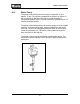
The heating circuit also contains a Temperature Activated Safety
Fuse. Should the temperature exceed a specific threshold due to
an operating fault, the fuse blows and interrupts power to the
element(s).
Should this fuse be blown, the cause must be located and resolved
before replacing the fuse.
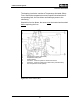
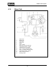
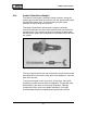
Figure 4-21: Steam Heater (2R1)
1 Temperature monitor (thermostat)
2 Temperature safety fuse
3 Heater element
4 Connector - Pressure system to steam valve in door
5 Connector - Pressure system from steam valve (solenoid valve)
6 PTC Temperature sensor (2R30)