Operating and Installation Instructions Ventilation Hood To prevent accidents and damage to the appliance, you must read these instructions before installing the appliance and using it for the first time. en-US M.-Nr.
Contents IMPORTANT SAFETY INSTRUCTIONS ................................................................ 4 Caring for the environment ................................................................................ 13 Guide to the appliance ........................................................................................ 14 Description of functions ..................................................................................... 16 Before using for the first time ..................................
Contents OdorFree Charcoal Filter ....................................................................................... 37 Resetting the filter saturation indicator for the charcoal filters......................... 38 Disposing of charcoal filters ............................................................................. 38 Installation............................................................................................................ Before installation.........................................
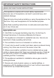
IMPORTANT SAFETY INSTRUCTIONS READ AND SAVE THESE INSTRUCTIONS This appliance complies with current safety requirements. Improper use of the appliance can lead to personal injury and material damage. Read all instructions before installing or using the appliance for the first time. Only use the appliance for its intended purpose. Keep these operating instructions in a safe place and pass them on to any future user. Appropriate use CAUTION: For General Ventilating Use Only.
IMPORTANT SAFETY INSTRUCTIONS Safety with children As with any appliance, close supervision is necessary when used by children. Please supervise children in the vicinity of the hood and do not let them play with it. The LED ClearView lighting is very intense. Ensure that especially babies/small children don't look into the light. Danger of suffocation! Ensure that any plastic wrappings, bags, etc. are disposed of safely and kept out of the reach of children.
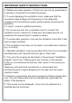
IMPORTANT SAFETY INSTRUCTIONS Reliable and safe operation of this hood can only be guaranteed if it has been connected to the electrical supply. To avoid damaging the ventilation hood, make sure that the connection data (voltage and frequency) on the data plate correspond to the building's power supply before connecting the appliance. If in doubt, consult a qualified electrician. Do not use a power bar or extension cord to connect the ventilation hood to electricity.
IMPORTANT SAFETY INSTRUCTIONS During installation, maintenance, and repair work, the ventilation hood must be disconnected from the electrical supply. It is only completely isolated from the electricity supply if one of the following applies: – The circuit breakers on the electrical service panel are tripped. – The screw-type fuses on the electrical service panel have been removed. – The power cord (if present) has been unplugged from the socket (pull the plug not the cord).
IMPORTANT SAFETY INSTRUCTIONS – b) NEVER PICK UP A FLAMING PAN - You may be burned. – c) DO NOT USE WATER, including wet dishcloths or towels - a violent steam explosion will result. – d) Use a fire extinguisher ONLY if: – 1) You have a class ABC extinguisher, and you know how to operate it. – 2) The fire is small and contained in the area where it started. – 3) The fire department is being called. – 4) You can fight the fire with your back to an exit.
IMPORTANT SAFETY INSTRUCTIONS Please note that the heat rising from the stovetop during cooking can cause the ventilation hood to become very hot. Do not touch the housing or the grease filters until the ventilation hood has cooled down.
IMPORTANT SAFETY INSTRUCTIONS Proper installation WARNING: TO REDUCE THE RISK OF FIRE, ELECTRIC SHOCK, OR INJURY TO PERSONS, OBSERVE THE FOLLOWING: – a) Installation work and electrical wiring must be done by qualified person(s) in accordance with all applicable codes and standards, including fire-rated construction. – b) Sufficient air is needed for combustion and exhausting of gases through the flue (chimney of fuel burning equipment to prevent back drafting.
IMPORTANT SAFETY INSTRUCTIONS Be sure to observe the information contained in the “Installation” section when mounting the ventilation hood. Metal parts can have sharp edges which may cause injury. Wear gloves to protect your hands from being cut. When installing the exhaust duct, only use pipes or tubes made of non-flammable material. These can be obtained from your Miele dealer or from Miele Technical Service.
IMPORTANT SAFETY INSTRUCTIONS FCC Declaration of Conformity These devices comply with FCC Rules Part 15. This equipment has been tested and found to be in compliance with the limits for a Class B digital device, pursuant to Part 15 of the FCC Rules of Operation and is subject to the following conditions: These devices may not cause harmful interference. These devices must accept any interference received, including interference that may cause undesired operation.
Caring for the environment Disposal of the packing material The cardboard box and packing materials protect the appliance during shipping. They have been designed to be biodegradable and recyclable. Ensure that any plastic wrappings, bags, etc. are disposed of safely and kept out of the reach of children. Danger of suffocation! Disposal of your old appliance Electrical and electronic appliances contain valuable materials.
Guide to the appliance 14
Guide to the appliance a Chimney extension b Chimney c Canopy d Control panel The symbols act as sensor-controlled buttons. To select a function, tap the button. An audible tone sounds briefly to confirm selection. e Grease filter f Spacer frame The spacer frame creates a shadow gap between the chimney and the ceiling. The hood can be installed with or without the spacer frame.
Description of functions The following functions are available on your ventilation hood, depending on the model: Vented mode The air is drawn in and cleaned by the grease filters and directed outside. Non-return flap A non-return flap in the ducting prevents the exchange of inside and outside air from occurring when the ventilation hood is not in use. The flap is closed when the ventilation hood is turned off.
Before using for the first time Selecting extraction mode or recirculation mode The ventilation hood can be operated with either extraction mode or recirculation mode. The power of the blower is adapted to suit the selected mode of operation. The ventilation hood is set up at the factory for recirculation mode. It has to be reset for extraction mode. To reset it for extraction mode, the filter saturation indicator for the charcoal filter(s) has to be deactivated. Switch off the blower and the lighting.
Before using for the first time Connecting via the app Switch the ventilation hood off. The Miele@mobile app can be used to connect to your network. Install the Miele@mobile app on your mobile device. Press and hold the B control. To log in you will need: 1. Your WiFi network password 2. Your ventilation hood password Touch the lighting control at the same time. 2 will light up constantly, 3 will flash on and off. The ventilation hood is ready for connection in the next two minutes.
Before using for the first time Connecting via WPS Your WiFi router must support WPS (WiFi Protected Setup). Switch the ventilation hood off. Press and hold the B control. Touch the lighting control at the same time. Start the WiFi connection on your WiFi router. When successfully connected, 2 and 3 will light up constantly. Quit connection mode on the ventilation hood by touching the delayed shutdown control . 2 will light up constantly, 3 will flash on and off.
Before using for the first time Signing out of WiFi (reset to factory settings) To set up a new WiFi connection, the existing WiFi connection must be disconnected. Touch the 1 control. Switch the ventilation hood off. 2 will light up constantly, 3 will flash on and off. Press and hold the 1 control. Touch the lighting control at the same time. With an existing WiFi connection, 2 and 3 will light up constantly. The ventilation hood is ready for disconnection during the next two minutes.
Before using for the first time Setting up Con@ctivity Con@ctivity is the direct communication system between an electric Miele cooktop and a Miele ventilation hood. It enables the ventilation hood to operate automatically depending on the operational state of a Miele cooktop with onset controls. Con@ctivity with direct wireless connection (Con@ctivity 2.0) Prerequisite: – Con@ctivity 2.0 enabled Miele cooktop – When a burner is turned on, the overhead lighting on the hood turns on automatically.
Before using for the first time Installing the Con@ctivity 2.0 stick Activating the ventilation hood See the relevant installation instructions provided with the Con@ctivity 2.0 stick. The cooktop and ventilation hood must be switched off. Activating the wireless connection The ventilation hood and the cooktop must be installed and operational. The wireless connection must be activated on the ventilation hood and the cooktop at the same time. Activation on the ventilation hood is described below.
Before using for the first time Finishing activation on the ventilation hood Touch the B control to activate Con@ctivity 2.0. When successfully connected, B will go out, and 2 and 3 will light up constantly. 2 will light up constantly, 3 will flash on and off. After a few seconds, 2 and 3 will light up constantly, B will flash on and off. The search for a wireless connection will start. Activating the cooktop While the ventilation hood is searching for a signal, start activating the cooktop.
Before using for the first time Activation failed If a wireless connection cannot be established despite activation of the Con@ctivity function on the ventilation hood and cooktop, the function must first be deactivated and then reactivated on both appliances. Deactivating the wireless connection Touch the 1 control to deactivate Con@ctivity 2.0. 2 will light up constantly, 3 will flash on and off. The cooktop and ventilation hood must be switched off.
Operation (Automatic mode) When Con@ctivity is active, the ventilation hood always operates in Automatic mode (see “Setting up Con@ctivity”). If you wish to manually operate the ventilation hood, see “Cooking without Con@ctivity”. Examples for power levels 1 to B Cooking with Con@ctivity (Automatic mode) Turn on a burner to the desired power setting. The overhead lighting will come on.
Operation (Automatic mode) Cooking process Switching off If, for example, you switch on a burner at the highest power setting to heat cookware in preparation for searing and then reduce the power level after approx. 10 seconds to 4 minutes*, a cooking process is recognized. Turn off all burners. The hood turns on automatically and, after the cooktop power level has been reduced, switches back to blower level 3, where it remains for approx. 5 minutes.
Operation (Automatic mode) Temporarily exiting Automatic mode To temporarily exit Automatic mode when cooking: Manually select a different blower level, or Manually turn the hood off, or Activate the delayed shutdown function on the ventilation hood. The blower will switch itself off after the selected delayed shutdown time, and the lighting will remain on. You can also operate the ventilation hood manually for a complete cooking process.
Operation (Manual mode) Cooking without Con@ctivity (Manual mode) Selecting the delayed shutdown time The ventilation hood can be operated manually if: It is advisable to run the blower for a few minutes after cooking has finished. This helps to neutralize any lingering vapors and odors in the air. – The Con@ctivity function is not activated. – You have temporarily deactivated the Con@ctivity function (see “Temporarily exiting Automatic mode”).
Operation (Manual mode) Dimming/switching the overhead lighting on/off The overhead lighting can be switched on and off and dimmed independently of the blower. Touch the lighting control briefly to switch it on or off. The lighting will switch on at maximum brightness. Power management The ventilation hood features a power management system to help save energy. The blower power level is reduced and the lighting is turned off automatically.
Operation (Manual mode) Turning power management on/off Safety shut-off Switch off the blower and the lighting. If power management has been deactivated, the ventilation hood will switch itself off automatically after 12 hours if it has been left on (blower and overhead lighting). Touch the delayed shutdown control for approx. 10 seconds, until 1 lights up in the power level display. Then touch in order: – the lighting control , – the 1 control, and then – the lighting control .
Operation (Automatic and Manual modes) Filter saturation indicator Switch off the blower and the lighting. The ventilation hood registers the length of time it has been operated. Touch the delayed shutdown control and the grease filter control at the same time. The filter saturation indicators show when the filters need to be cleaned or changed by lighting up the grease filter symbol or charcoal filter symbol .
Operation (Automatic and Manual modes) Adjusting or deactivating the filter saturation indicator for the charcoal filter Checking the filter saturation indicator The charcoal filter is needed for recirculation mode. Before the set operating time has run out, you can check what percentage of the time has elapsed. You can set the filter saturation indicator to suit your cooking habits. Press the On/Off control to turn the blower on. It has to be deactivated for extraction mode.
Energy-saving tips This hood operates in a very efficient and energy-saving manner. The following will help you to save even more energy when using it: – Ensure that there is sufficient ventilation in the kitchen when cooking. If there is insufficient air flow during vented mode, the hood cannot operate efficiently, causing increased operating noise levels. – Always cook with the lowest possible setting.
Cleaning and care WARNING: TO REDUCE THE RISK OF FIRE, ELECTRIC SHOCK, OR INJURY TO PERSONS, OBSERVE THE FOLLOWING: Before cleaning or servicing the hood, disconnect it from the power supply, see “IMPORTANT SAFETY INSTRUCTIONS”. Stainless steel housing General information The surfaces and control buttons are susceptible to scratching and chipping. Observe the following cleaning instructions. Clean all surfaces and control buttons using warm water and liquid dish soap. Apply with a sponge cloth.
Cleaning and care Grease filters Risk of fire! Oversaturated grease filters are a fire hazard. Clean the grease filters at regular intervals. Removing the grease filters When handling the grease filter, be careful not to drop it. This can result in damage to the filter and the cooktop below. Make sure you hold the filter securely at all times when handling it. The reusable metal grease filters in the appliance remove the solid particles contained in kitchen vapors (grease, dust, etc.
Cleaning and care Unsuitable cleaning agents After cleaning Unsuitable cleaners can cause damage to the filter surfaces if used regularly. Do not use any of the following: After cleaning, leave the filters on an absorbent surface to dry.
Cleaning and care Resetting the filter saturation indicator for the grease filters Once cleaning is complete, the filter saturation indicator must be reset. While the blower is turned on, touch the grease filter control for approx. 3 seconds, until only the 1 is flashing. The grease filter symbol goes out. When cleaning the grease filters before the full operating time has elapsed: Touch the grease filter control for approx. 6 seconds, until only the 1 is flashing.
Cleaning and care When to change the OdorFree Charcoal Filter Replace the charcoal filter when it no longer absorbs kitchen odors effectively. It should be replaced at least every 6 months. The filter saturation indicator reminds you to regularly clean the charcoal filter by illuminating the charcoal filter symbol . Resetting the filter saturation indicator for the charcoal filters After changing the charcoal filters, the filter saturation indicator must be reset.
Installation Before installation Before installing the appliance, read all of the information contained in this chapter and also in the “IMPORTANT SAFETY INSTRUCTIONS” section. Installation parts 4 extension piece holders for aligning and securing the telescopic chimney 4 screws M³/₁₆“ x ⁵/₁₆” (M4 x 8.5 mm) for securing the extension piece holders. 4 screws, ¹/₄“ x 4 ⁵/₁₆” (7 x 110 mm) and 4 plugs, ³/₈“ x 3 ¹/₈” (10 x 80 mm) for securing the ventilation hood to the ceiling (not for use in USA / CDN).
Installation Appliance dimensions a Mounting area for the exhaust ducting and power cable. In recirculation mode, only the power cord is required.
Installation f A power cord is required to connect the hood to the socket in the ceiling. With extraction mode flexible ducting is also required. Exhaust connection 6" (150 mm) Distance between cooktop and ventilation hood (S) Provided a larger distance is not given by the manufacturer of the cooktop, follow the minimum safety distances between a cooktop and the bottom of the hood. Please also observe the information contained in the “IMPORTANT SAFETY INSTRUCTIONS” section.
Installation Installation recommendations Structural support – A distance of at least 26" (660 mm) is recommended above electric cooktops to provide more workspace and easier cooking under the hood. – When selecting an installation height, always take the user height into consideration. Users should have ample space to work comfortably on the cooktop and reach the ventilation hood controls with ease.
Installation 85 5/8" m 22 /8" 0 8 22 0m mm For vented mode: dai3435aus Draw two intersecting lines on the ceiling. – Place a section of the exhaust ducting in the ceiling and feed it down through the cross-sectional area as illustrated. Exhaust ducting of approx. 27 ⁹/₁₆" (700 mm) length is required between the ceiling and the hood exhaust socket. – Secure the exhaust ducting to the exhaust socket, e.g. with a hose clip (available as an optional accessory) on flexible ducting.
Installation Use a knife to release the four spacers and the two covers from the spacer frame supplied. Drill four holes ³/₈“ (10 mm), approx. 4 ¹/₂” (115 mm) deep for the plugs supplied. Use the spacer frame as a drilling template. Place it on the ceiling with the arrows pointing forwards. Using the notches, align the spacer frame on the intersecting lines and make pencil marks for the drill holes.
Installation The spacer frame can be installed between the chimney and the ceiling. This creates a shadow which gives the illusion of a gap between the ceiling and the chimney. This is useful if the ceiling is not level or is uneven. The hood is aligned vertically with the spacers supplied. Visual irregularities between the chimney and the ceiling are then concealed by the shadow. Mount the spacer frame onto the installation frame.
Installation Hang the installation frame on the four screws. The front of the frame is marked with a “V”. If using the spacer frame, place the two covers into the fixing holes. 46 Align the installation frame and secure it with the screws. The spacers, which were removed from the spacer frame at the start, can be used to align the hood vertically.
Installation Holding the installation frame securely, remove the two fixing screws and extend the installation frame to its maximum length. Replace the screws. The directional unit from recirculation kit DUI 32 (optional accessory) is installed for recirculation mode (RM): Bend the four retaining tabs on the installation frame outward. Place the power cord inside the installation frame. Fit the directional unit as shown, noting the marking on the front.
Installation Secure the exhaust socket to the hose using a hose clip. Secure the hose to the directional unit socket using a hose clip. Check that the hose is held securely. Push the telescopic chimney over the installation frame: – with the recirculation grilles at the bottom for vented mode (AE), – with the recirculation grilles at the top for recirculation mode (RM). Bend the two retaining tabs outwards to prevent the telescopic chimney from slipping down again.
Installation Fit the four telescopic chimney clamps. When the screws are tightened, the clamps spread out and push the telescopic expansion piece upwards. Tighten the screws only until the top edge of the telescopic chimney is evenly aligned with the ceiling or the spacer frame. Bend back the two retaining tabs. Push the chimney over the telescopic extension piece and bend the retaining tabs outward again to prevent the chimney from slipping down again.
Installation A non-return flap is supplied with the hood or is already fitted in the exhaust socket of the motor unit (depending on model). With vented mode (AE) insert the non-return flap in the exhaust socket if your ducting system is not equipped with one. Recirculation mode (RM) does not require the non-return flap to be inserted. If there is one present, it should be removed. Hang the hood on the brackets, making sure that the controls are at the front.
Installation Connect the power cord. See “Electrical connection.” Unscrew both screws from the installation frame again. Place the exhaust ducting onto the exhaust socket. The canopy can now be adjusted to the desired height, observing the permissible height ranges: – With vented mode: upwards as far as it will go, downwards only to the “A” marking. – With recirculation mode: upwards as far as the “U”, downwards as far as it will go. Follow the instructions in “Appliance dimensions.
Installation Raise the canopy to the desired height and secure it with the screws. Hold the chimney securely, bend back the retaining tabs and carefully lower it. The chimney will locate in the cut-out in the canopy.
Installation With recirculation mode (RM) ventilation hoods, insert the OdorFree Charcoal Filter. Remove the grease filters from the hood. Insert the safety screw on the inside. Carefully remove the protective foil from the grease filters. Reinsert the grease filters.
Air venting WARNING: Danger of toxic fumes. Gas cooking appliances release carbon monoxide that can be harmful or fatal if inhaled. To reduce the risk of fire and to properly exhaust air, the exhaust gases extracted by the hood should be vented outside of the building only. Do not vent exhaust air into spaces within walls or ceilings or in attics, crawl spaces or garages. To reduce the risk of fire, only use metal ductwork.
Air venting Condensate trap In addition to insulating the exhaust duct, we recommend installing a condensate trap to collect and evaporate any condensate which might accumulate. Condensate traps are available for exhaust ducts with a diameter of 5" (125 mm) or 6" (150 mm). When installing a condensate trap, make sure that it is positioned vertically and, if possible, directly above the hood outlet duct collar. The arrow on the housing indicates the direction of airflow.
Electrical connection WARNING: TO REDUCE THE RISK OF FIRE, ELECTRIC SHOCK, OR INJURY TO PERSONS, OBSERVE THE FOLLOWING: All electrical work should be performed by a qualified electrician in strict accordance with national regulations (for USA: ANSI-NFPA 70) and local safety regulations. Installation, repairs and other work by unqualified persons could be dangerous. Ensure that power to the appliance is OFF while installation or repair work is performed.
Service and warranty For faults that you cannot resolve on your own, please contact your Miele dealer or Miele Technical Service. MieleCare The telephone number for Miele is listed at the back of these instructions. MieleCare, our Extended Service Contract program, gives you the assurance of knowing that your appliance investment is covered by 5 years of worry free ownership.
Technical data Blower motor Overhead lighting Total connected load Supply voltage, frequency Fuse Weight 350 W 4x3W 362 W 120 V AC, 60 Hz 15 A 77 lbs (35 kg) WiFi module Frequency band Maximum transmission power 2.412–2.462 GHz < 100 mW ZigBee® module Frequency band Maximum transmission power 2.405–2.
Please have the model and serial number of your appliance available when contacting Technical Service. U.S.A. Canada Miele, Inc. Importer Miele Limited National Headquarters 9 Independence Way Princeton, NJ 08540 Phone: 800-843-7231 609-419-4298 Fax: www.mieleusa.com Technical Service & Support Phone: 800-999-1360 888-586-8056 Fax: TechnicalService@mieleusa.com International Headquarters Miele & Cie.
DA 6698 D en-US M.-Nr.