Operating and Installation Instructions External Blower DAG 1000 To prevent accidents and appliance damage, read these instructions before installation or use. en - US, CA M.-Nr.
Contents IMPORTANT SAFETY INSTRUCTIONS. . . . . . . . . . . . . . . . . . . . . . . . . . . . . . . . . 4 Functional description . . . . . . . . . . . . . . . . . . . . . . . . . . . . . . . . . . . . . . . . . . . . . 6 Appliance dimensions . . . . . . . . . . . . . . . . . . . . . . . . . . . . . . . . . . . . . . . . . . . . . . 7 Installation . . . . . . . . . . . . . . . . . . . . . . . . . . . . . . . . . . . . . . . . . . . . . . . . . . . . . . . 8 Preparation . . . . . . . . . . . . . . . . . . . .
IMPORTANT SAFETY INSTRUCTIONS READ AND SAVE THESE INSTRUCTIONS Keep these operating instructions in a safe place and pass them on to any future user. Read these Instructions carefully before installing or using the Ventilation System. ~ This appliance is intended for residential use only. Use the appliance only for its intended purpose. ~ This appliance complies with current safety requirements. Improper use of the appliance can lead to personal injury and material damage.
IMPORTANT SAFETY INSTRUCTIONS ~ d) Before connecting the appliance to the power supply make sure that the voltage and frequency listed on the data plate correspond with the household electrical supply. This data must correspond to prevent appliance damage. If in doubt consult a qualified electrician. Installation ~ e) Installation work and repairs should only be performed by a qualified technician in accordance with all applicable codes and standards.
Functional description The external blower should only be used in combination with Miele ventilation systems DA 6480 or DA 6490. It must be mounted outside the kitchen on an external wall or on the roof. The external blower is connected to the ventilation system by an exhaust duct and power cord. It is operated by means of the ventilation system control panel.
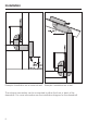
Appliance dimensions a Exhaust air connection b Power cord feed-through (strain relief) 7
dai2749 Installation Example: Installation on an external wall Example: Installation on a roof The exhaust connection can be connected to either the front or back of the downdraft. For more information see the installation diagram for the downdraft.
Installation ^ Remove all packaging. ^ Mount the external blower on the external wall using four suitable screws. ^ Unscrew and remove the six screws on the blower cover. ^ Seal the screw heads. Preparation ^ Unscrew the two screws on the terminal box and remove the cover. Install a UL/CSA-approved cable clamp in the power cord feed-through (strain relief). Locate it so that it is accessible from the blower. Installation on a roof ^ Close the terminal box and the replace the blower cover.
Installation ^ The external blower and the ventilation system are connected by a 10" (254 mm) exhaust duct C (see "Air extraction"). Mount the provided connection plate on the ventilation system (see installation instructions DA 6480, 6490). ^ Install a UL/CSA-approved power cord (see "Electrical connection"). If unsure or unfamiliar with these installation procedures, please contact a qualified contractor. ^ Remove the roof shingles at the installation location.
Air extraction ,WARNING Danger of toxic fumes. Gas cooking appliances release carbon monoxide that can be harmful or fatal if inhaled. To reduce the risk of fire and to properly exhaust air, the exhaust gases extracted by the hood should be vented outside of the building only. Do not vent exhaust air into spaces within walls or ceilings or in attics, crawl spaces or garages. To reduce the risk of fire, only use metal ductwork.
Electrical connection ,WARNING TO REDUCE THE RISK OF FIRE, ELECTRIC SHOCK, OR INJURY TO PERSONS, OBSERVE THE FOLLOWING: All electrical work should be performed by a qualified electrician in strict accordance with national regulations (for USA: ANSI-NFPA 70) and local safety regulations. Installation, repairs and other work by unqualified persons could be dangerous. Ensure that power to the appliance is off while installation or repair work is performed.
Electrical connection Important Maximum load . . . . . . . . . . . . . . . 210 W The ventilation system must be hard wired as follows: Voltage . . . . . . . . . . . . . . . . . . . . . 120 V N (neutral) L1 (live) WHITE BLACK Ground screws GND (ground) Downdraft wiring Frequency . . . . . . . . . . . . . . . . . . 60 Hz Circuit Rating . . . . . . . . . . . . . . . . . 15 A Twist-on connectors Motor wiring GREEN-YELLOW dai2748 Black wire: . . . . . . . connect to L1 (live) White wire: . . . . .
After Sales Service Repairs In the event of a fault which you cannot easily fix yourself, please contact the Miele Technical Service Department. ^ When contacting the Technical Service Department, please have the model and serial number of your appliance available. These can be found on the data plate located on the housing above the connection box.
Caring for the environment Disposal of packing material Disposal of an old appliance The cardboard box and packing materials protect the appliance during shipping. They have been designed to be biodegradable and recyclable. Please recycle. Old appliances may contain materials that can be recycled. Please contact your local recycling center about the possibility of recycling these materials. ,DANGER Ensure that any plastic wrappings, bags, etc.
Alteration rights reserved / 1711 M.-Nr. 07 915 550 / 02 INFORMATION IS SUBJECT TO CHANGE. PLEASE REFER TO OUR WEBSITE TO OBTAIN THE MOST CURRENT PRODUCT SPECIFICATIONS, TECHNICAL & WARRANTY INFORMATION.