Installation instructions Dishwasher To prevent accidents and machine damage, read these instructions before installation or use. UV M.-Nr.
Contents IMPORTANT SAFETY INSTRUCTIONS . . . . . . . . . . . . . . . . . . . . . . . . . . . . . . . . . 3 INSTRUCTIONS IMPORTANTES SUR LA SÉCURITÉ . . . . . . . . . . . . . . . . . . . . . 5 Caring for the environment . . . . . . . . . . . . . . . . . . . . . . . . . . . . . . . . . . . . . . . . . . 7 Disposal of the packing material . . . . . . . . . . . . . . . . . . . . . . . . . . . . . . . . . . . . . . . 7 Disposal of an old machine . . . . . . . . . . . . . . . . . . . . . . . . . . . . . . . . . .
IMPORTANT SAFETY INSTRUCTIONS Installation Installation, maintenance and repair work should be by a Miele authorized service technician. Work by unqualified persons could be a hazard and may void the warranty. This equipment is not designed for maritime use or for use in mobile installations such as caravans or aircraft. However, under certain conditions it may be possible for an installation in these applications.
IMPORTANT SAFETY INSTRUCTIONS Electrical safety Child safety Before installation, make sure the voltage and frequency listed on the data plate correspond with the household electrical supply. This data must correspond to prevent injury and machine damage. Consult a qualified electrician if in doubt. Ensure that any plastic wrappings, bags etc. are disposed of safely and kept out of the reach of babies and young children.
INSTRUCTIONS IMPORTANTES SUR LA SÉCURITÉ Installation L’installation et les travaux de réparation et d’entretien doivent être effectués par un technicien de service autorisé Miele. Les travaux effectués par des personnes non qualifiées, pourraient être dangereux et faire annuler la garantie. Cet équipement n’a pas été conçu pour usage maritime ou pour les installations mobiles telles que les roulottes ou les avions.
INSTRUCTIONS IMPORTANTES SUR LA SÉCURITÉ Sécurité électrique Sécurité des enfants Avant l’installation, s’assurer que la tension et la fréquence énumérées sur la plaque signalétique correspondent à la source d’électricité de la résidence. Ces données doivent correspondre afin d’éviter de vous blesser et d’endommager l’appareil. Consulter un électricien qualifié si vous avez des doutes. S’assurer de disposer de tous les emballages de plastique, sacs etc.
Caring for the environment Disposal of the packing material The cardboard box and packaging protect the appliance during shipping. These materials are biodegradable and recyclable. Please recycle. Ensure that any plastic wrappings, bags etc. are disposed of safely and kept out of the reach of children. Danger of suffocation! Disposal of an old machine Old appliances may contain materials that can be recycled. Please contact your local recycling authority about the possibilty of recycling these materials.
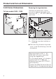
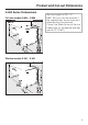
Product and Cut-out Dimensions G 600 Series Dishwashers Full size models G 636 - G 698 Removing the leg extensions The black leg extensions can be removed to reduce the height of the machine to 32 1/4" - 33" (819 - 838 mm) (see Inset). A = Black leg extension (removable) B = White leg (must be installed on machine). ^ After removing the black leg extensions, screw the white legs onto the dishwasher. Machine heights of 33 1/4" - 34" (845- 864 mm) are not possible using the supplied legs.
Product and Cut-out Dimensions G 800 Series Dishwashers Full size models G 836 - G 898 Machine heights of 35" - 37" (889 - 940 mm) can be obtained if the supplied legs are removed and extended legs are attached. Contact the Miele Technical Service Department for the appropriate legs (part # 02 702 601).
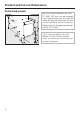
Product and Cut-out Dimensions Prefinished models Machine heights between 35" and 37" (889 - 940 mm) can be obtained if the supplied legs are removed and extended legs are attached. Please contact the Miele Technical Service Department for the appropriate legs (part # 02 702 601). ,To ensure stability, this dish- washer should only be installed under a continuous countertop and securely fastened.
Installation 1. Install the steam deflector A stainless steel steam deflector is supplied to protect the countertops from steam and condesation when the dishwasher is opened. If the countertop is made of Corian®, granite, marble or other solid, waterproof material, the steam deflector is not required. If the counter is made of different materials, the steam deflector should be positioned so that it covers the edge where the materials are joined.
Installation 2. Install the mounting brackets 3. Install the slide skis To ensure stability, this dishwasher should be securely attached to the countertop with the two mounting brackets included. Two slide skis are included and should be installed on the feet of the dishwasher before the machine is pushed under the countertop. This will allow the machine to slide easier, protect the floor, and allow adjustment of the rear leveling legs from the front of the machine.
Installation 4. Install the dishwasher under the countertop The dishwasher must be installed so that the water and electricity supplies can be accessed through an adjacent cabinet. The supplies must not be located behind the machine. The floor of the cut out where the dishwasher will be installed should be even in height with the surrounding kitchen floor. Plywood can be secured to the floor to make the two areas even.
Installation 5. Level the legs ^ The rear leveling legs can be adjusted with a T20 Torx screwdriver by turning the screws at the front of the slide skis. To raise the machine turn clockwise. To lower the machine turn counter clockwise. Several turns may be needed to set the correct height. Do not use a power screwdriver. ^ Adjust the front leveling legs by pushing on the feet with a slotted screwdriver. ^ Tipping the machine slightly backwards, if possible will make adjusting the front legs easier.
Installation 6. Install the control panel Dishwashers with a selector knob ^ Press the "On/Off" button in and place the cover, a, over the push button. ^ Insert the drying vent grill (if applicable), b, into its opening. ^ Position the control panel, c, and fasten it from the inside of the door, d, using the six screws provided. ^ Align and press the knob onto its shaft, e.
Installation Dishwashers with insertable push buttons ^ Press the "On/Off" button in and place the cover, a, over the push button. ^ Insert the drying vent grill, b, into its opening. 16 ^ Position the control panel, c, and fasten it from the inside of the door, d, using the six screws provided. ^ Insert the other button covers, e and f, into their openings.
Installation Dishwashers with fixed push buttons ^ Press the "On/Off" button in and place the cover, a, over the push button. ^ Push the drying vent grill, b, into its opening. ^ Position the control panel, c, and fasten it from the inside of the door, d, using the six screws provided.
Installation 7. Align the control panel The control panel should be aligned with the drawer fronts of the adjoining kitchen cabinets by adjusting the filler strips. ^ After adjusting the control panel height, cut off the plastic screw excess. Control Panel Height 4 1/2" control panel with(112 mm): out filler strips, 5 3/4" (145 mm): control panel with four filler strips, 6" (154 mm): using a fifth filler strip (optional accessory).
Installation 8. Install the custom door panel A custom door panel matching the kitchen cabinetry can be installed using the provided templates and bracket. As long as the panel length calculated is within the Range of Panel Sizes listed, the custom panel should fit without a problem.
Installation Maximum panel weight A custom door panel must not exceed the listed maximum weight. An overweight panel will distort the door springs causing the dishwasher door to fall when opened. G 600 door panel G 800 door panel Plastic control 13 lbs panel (5.9 kg) 12 lbs (5.5 kg) Stainless Steel 10.5 lbs control panel (4.8 kg) 9 lbs (4.
Installation ^ Place a template on each end of the mounting bracket as shown, making sure the rule marks face the outside of the bracket. ^ Slide the bracket up or down until the oblong holes on the machine door line up with the oblong holes on the template (shown in inset a). ^ Draw a line on each template that is even with the top edge of the adjacent cabinet door (inset b). ^ Remove the bracket from the door.
Installation ^ Tape the bracket to the door panel to hold it in place while the mounting holes are drilled. ^ Drill pilot holes for the screws using a 3 /32" (2.5 mm) bit. ^ Attach the bracket to the panel using the 6 screws provided. ^ Remove the templates. Save the templates for future use in case a new door panel needs to be installed.
Installation ^ Push up one side of the door panel until it touches the filler strips (or control panel if filler strips are not used) and lightly tighten the T20 Torx screws on the corresponding edge of the machine door. Do not use a power screwdriver. ^ Repeat the process with the other side of the door panel. ^ Shut the door. ^ Attach the panel to the dishwasher by aligning the bracket tabs with the slots on the door. ^ Check that the door panel is adjusted correctly.
Installation If the adjacent cabinetry (or appliance) does not have drawers and alignment to a drawer line is not possible: ^ Hang the bracket on the machine door, without the templates. Tighten the four locking screws on the edges of the door panel. ^ Close the door. ^ Measure the distance from the adjacent cabinet’s (or appliance) door bottom to the bottom of the mounting bracket (X). ^ Draw a line on the rear of the door panel (X) inches up from the bottom.
Installation ^ Push up one side of the door panel until it touches the filler strips (or control panel if filler strips are not being used) and lightly tighten the T20 Torx screws on the corresponding edge of the machine door. Do not use a power screwdriver ^ Repeat the process with the other side of the door panel. ^ Shut the door. ^ Attach the panel to the dishwasher by lining up the bracket tabs with the slots on the door. ^ Check that the door panel is adjusted correctly.
Installation 9. Secure the dishwasher ^ Open the dishwasher door. If the steam deflector is installed, the mounting bracket holes must align with the slots in the steam deflector. ^ Using flat head screws, secure the dishwasher to the countertop by screwing through both the mounting bracket and the steam deflector. 26 Make certain that the white rubber seal located at the top, outer edge of the dishwasher is tight against the bottom of the countertop.
Installation For openings exactly 17 3/4" (45 cm) or 23 5/8" (60 cm) wide: ,The side mounting holes should only be used for securing the dishwasher if the opening is exactly 17 3/4" (45 cm) wide (slim line models) or 23 5/8" (60 cm) wide (full size models). Use of this method on larger openings can damage the machine and cause leaks. Be careful not to screw into an adjacent appliance. ^ Open the dishwasher door and remove the caps covering the mounting holes on the outer edge of the wash cabinet.
Installation 10. Adjust the door springs ^ Open the dishwasher door halfway. If the door remains in this position when released, the springs are adjusted correctly. If the door drops, the tension on the springs needs to be increased. If it closes on its own, the tension on the springs need to be decreased. ^ To adjust the door springs use a T20 Torx or a small slotted screwdriver and turn the screw located behind the door in the upper front strip, on the left hand side of the dishwasher.
Installation 11. Make the plumbing connections An air gap is built into the water inlet system to prevent potable water from mixing with waste water. The dishwasher can heat its own water to the temperatures required by the wash program. This allows the option of connecting the machine to either a hot or cold water source. ^ For lowest energy consumption connect the dishwasher to a cold water source.
Installation Existing plumbing: If the standard 3/8" copper plumbing for a dishwasher already exists with a compression fitting and valve as pictured: ,Do not cut the intake hose. If the ^ Cut the 3/8" copper tubing after the valve. hose is cut, the dishwasher will not work. There will be a water leak and you could be injured. If the hose is too long, coil it neatly and place it behind the machine.
Installation Drainage system specifications: The machine comes equipped with: – A 5 ft. long (1.5 m) flexible drain hose with an internal diameter of 7/8" (22 mm). Drain hose extensions can be ordered from Miele’s Technical Service Department. – A built-in swivel connector allowing the drain hose to be routed in any direction. – A built-in mechanical non-return valve on the discharge side to prevent waste water from flowing back into the dishwasher.
Installation Venting the drainage system Additional note If the dishwasher drain hose is connected to a floor drain or to a drain pipe that is less than 8" (20 cm) above the floor, the drain must be vented. Otherwise the water inside the dishwasher may siphon out during the wash program. Since all Miele dishwashers are equipped with an odor trap and nonreturn valve, the drain hose can be connected directly to the drain pipe as illustrated.
Installation 12. Make the electrical connection GROUNDING INSTRUCTIONS THIS APPLIANCE MUST BE GROUNDED. In the event of a malfunction or breakdown, grounding will reduce the risk of electric shock by providing a path of least resistance for the electrical current. This appliance is equipped with a cord having an equipment grounding conductor and a grounding plug. The plug must be plugged into an appropriate outlet that is installed and grounded in accordance with all local codes and ordinances.
Installation Power outlet Permanent Connection (Hard Wiring) The power outlet for the appliance must be installed within a cabinet, on a wall adjacent to the undercounter space in which the dishwasher is located. An opening through the partition between the compartments of 1 1/2" (3 to 4 cm) can be made to allow the plug to pass through. For hard wiring, the power cord must be disconnected from the terminal box located at the lower left front of the dishwasher, behind the toekick and service panel.
Installation 13. Test the unit Once the dishwasher is level and secured it should be tested. ^ Remove all packing and literature from inside the unit. ^ Check for any leaks, odd noises and flashing / lit fault indicators on the control panel. See the "Operating Instructions / Frequently asked questions" if there is a problem. The yellow Child Safety Lock key hung on the upper basket must be removed before operating the dishwasher. If not removed, the key could become lodged in the circulation pump.
Installation 14. Install the toekick For installations using a continuous toekick or a cabinet matching toekick Before installing the toekick, measurements must be taken to ensure that the toekick will not interfere with the complete opening of the dishwasher door. If the door panel hits the toekick when the dishwasher door is opened, the toekick must be cut shorter or recessed deeper.
Installation For installations using the included plastic toekick G 600 Series dishwasher G 800 Series dishwasher and "U" model ^ Insert the mounting bracket with the flange pointing toward the center of the machine. ^ Insert the mounting bracket with the flange pointing toward the outside of the machine. ^ Push the mounting brackets in as far as possible by releasing the tension on the spring clip (see illustration).
Installation The included toekick will fit without modification if the machine is set to its maximum height and the toekick is recessed as far as possible (4" / 10 cm). If the machine height is less than maximum, or if the toekick is not recessed 4" (10 cm), the toekick must be shortened. ^ Screw the toekick onto the installed brackets, with the cutting lines towards the top, and pull out evenly and slowly until it aligns with the toekick of the adjoining cabinets.
Installation ^ Carefully open the dishwasher door until it hits the toekick. ^ Using the front lower edge of the door panel as a guide, draw a line across the toekick. ^ Unscrew and remove the toekick. ^ If one of the cutting lines is close to the line just drawn, score the front of the toekick, and snap off the excess, otherwise, trim the toekick along the line using a saw. ^ Screw the toekick back onto the brackets, with the cut edge at the bottom.
Alteration rights reserved (NovoplusB,P,S) / 2702 This bio-friendly paper was bleached without the use of chlorine. M.-Nr.