
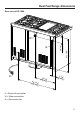
Installation Manual


Anti-tip device
74
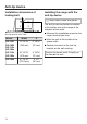
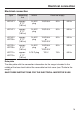
Installation dimensions of
locking bolt
X
Anti-tip device, front view
Model Width X
HR 1421
HR 1622
HR 112x
HR 192x
29 15/16"
(760 mm)
3 13/16"
(97 mm)
HR 113x
HR 193x
35 15/16"
(913 mm)
3 13/16"
(97 mm)
HR 195x 47 15/16"
(1218 mm)
3 1/4"
(82 mm)
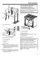
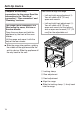
Installing the range with the
anti-tip device
W
ear safety shoes and gloves.
The anti-tip device should be installed
at the bott
om rear of the range at the
midpoint of the width.
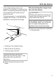
Measu
re the installation space for the
range close to floor level.
Mark the wall at the middle of the
space width.
P
osition the notch of the anti-tip
bracket on the wall marking.
The anti-tip device must fit tightly on
the floor or the wall.