
Installation Manual
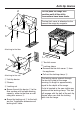

Anti-tip device
75
1
3
2
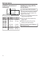
Attaching to the floor
1
3
2
Attaching to the wall
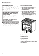
a
Anti-tip device
b
Screws
c
Locking nut
Secur
e the anti-tip device to the
floor surface with suitable bearing
capacity, either to the floor or wall.
using four screws .
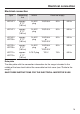
Scr
ew the locking nut to the bolt,
see the "Installation dimensions of
locking bolt" table.
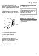
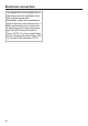
Do not push the range into
position until all the utility
connections have been made.
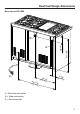
The toe-kick cover is attached to the
base of the range by magnets.
21
a
Toe-kick cover
b
Locking clamp
Remo
ve the toe-kick cover from
the appliance.
P
ull out the locking clamp .
The locking clamp extends through
the t
oe-kick plate of the range
housing. Its length is approximately
equal to the depth of the range.
A slot is located in the non-visible rear
section of the locking clamp. This slot
will engage with the bolt of the anti-tip
device when you slide the locking
latch in
to the range.