Installation Instructions Information is subject to change. Please refer to our website to obtain the most current product specification, technical & warranty information. K1803 SF, K1903 SF To prevent accidents and machine damage read these instructions before installation or use.
Caring for the environment Disposing of the packaging materials The packaging is designed to protect the appliance from damage during transportation. The packaging materials used are selected from materials which are environmentally friendly for disposal and should be recycled. Ensure that any plastic wrappings, bags, etc. are disposed of safely and kept out of the reach of children. Return the packaging to your dealer.
Installation Installation site Have the appliance installed by a qualified technician, according to the enclosed installation instructions. WARNING This appliance is top-heavy and must be secured to prevent it from tipping forward. Keep the door closed until the appliance is completely installed and secured as per the installation instructions. Empty weight of your machine: K 18x3 SF . . . . . . . . . 476 lbs (216 kg) K 19x3 SF . . . . . . . . .
Installation Important! When there is high humidity a build-up of condensation on the outer surfaces of the appliance can occur.This can cause the surfaces to corrode.To prevent this, it is advisable to install the appliance in a dry and/or an air-conditioned room with sufficient ventilation.Please ensure that doors close and seal properly after installation and that the appliance is installed in accordance with these installation instructions and and with the required ventilation openings.
Installation Base Ventilation A fully loaded appliance is very heavy. The load-bearing capacity of your floor must meet the following requirements: The air intake and outlet must not be blocked or covered in any way. They also need to be dusted/cleaned on a regular basis. K 18x3 SF . . . . . . . . 1,056lbs (479 kg) K 19x3 SF . . . . . . . .
Installation Stainless steel panels Side-by-side Stainless steel door panels and toe-kick covers are available from Miele. This appliance can be installed "side-by-side" with another fridge/freezer using a "Merging Kit". Installation options The "Merging Kit" is available from Miele. There are many different installation options. These are limited only by the design of the kitchen. The door hinge cannot be exchanged.
Installation Installation with partition using the "Merging Kit" The minimum thickness of the partition is 5/8" (16 mm). Side panels If one side of the appliance is visible, a side panel must be used. The side panel must be firmly secured to the wall, the floor and the overhead furniture/fixtures before the appliance is placed in the cavity. The dimensions of the side panel are taken from the opposite wall of the installation space.
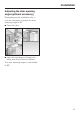
Installation Adjusting the door opening angle (optional accessory) Depending on the installation site, it may be necessary to adjust the door opening angle to 90°. ^ Open the door. ^ Insert the banking pin through the holes and drive in with a hammer. The door opening angle is now limited to 90°.
Dimensions Door dimensions (open min.
Dimensions Niche dimensions A B K 18X3 SF 30 ½" (774.
Dimensions Power supply 1. Power supply A K 18X3 SF 15" (381 mm) K 19X3 SF 18" (458 mm) ,Power bars or extension cords are not safe (risk of fire).
Installing the appliance Before you begin Read these instructions completely and carefully. Have the appliance installed by a qualified technician, according to the enclosed installation instructions. Tools needed for installation – Cordless screwdriver – Torx screwdriver – Hammer drill – Wood drills in different sizes – Hammer – Rachet 5/16" (8 mm) To reduce the risk of injury or damage to the product, two people should be used for installation.
Installing the appliance Aligning the housing unit Check the installation niche To ensure a safe, trouble-free installation and the best possible cosmetic result, check to be sure that the installation space complies with the installation requirements. ^ Check the base (see "Installation"). ^ Check the dimensions of the cavity. ^ Check that the cavity is square. ^ Check the location of the power outlet. The housing unit must be carefully aligned using a spirit level before installing the appliance.
Installing the appliance There are transportation safety devices inside the appliance to protect the shelves and storage compartments until installation is complete. Do not remove them, or parts may be damaged. ^ Check the appliance for damage in transit. Do not install the appliance if it is visibly damaged. If in doubt, contact your dealer. RemoteVision module installation (optional accessory) Always disconnect the appliance from the power supply when performing installation, maintenance or service work.
Installing the appliance ^ Push the module into the slot until it locks into place. ^ Connect the appliance to the power supply and turn it on. After several seconds the indicator light e will come on. The indicator light will display different colors one after the other; any control light at the end indicates that the module was correctly installed. If the indicator light does not come on, installation of the module was unsuccessful. In that case, repeat the process.
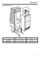
Installing the appliance Mounting Accessories The mounting accessories needed for installing the appliance into the niche are included in the packaging. Several plastic bags are included which are numbered alphabetically. The bag needed for each step will be marked with its respective letter. Anti-tip brackets The anti-tip brackets a keep the appliance safely secured in the installation niche b and prevent it from tipping. Two anti-tip brackets are recommended for each appliance.
Installing the appliance In a cabinet without a back wall ^ Now attach the installation niche to the wall. The built-in cabinet must be secured to the wall behind it with several screws. In a cabinet with a back wall ^ screw the cabinet to the wall behind it in several places using suitable mounting brackets. For this, use suitable plugs/screws depending on the type of wall. ^ screw the back wall of the cabinet in several places directly to the wall behind it.
Installing the appliance Securing an alternative anti-tip device – The beam must cover the appliance by at least 2" (50.8 mm). ^ Mark the installation height (lower edge of the beam) on the rear wall of the niche. ^ Select screws according to the thickness of the wooden beam. Example: 3 ½" (89 mm) screw for 2x4 beam. ^ Determine the number of screws based on the cavity width, to ensure that the beam will be attached securely.
Installing the appliance Sliding the appliance into the installation space If a side-by-side installation is desired, connect the two appliances together. See the Installation Manual included with the "Merging Kit". ^ Plug the appliance into the power outlet a. The plug of the appliance should be easily accessible after installation. If the plug is not accessible after the appliance has been installed, disconnection from the power supply should be completed via the circuit breaker.
Installing the appliance Aligning the appliance ^ Align the appliance with the custom front. ^ Unscrew the height-adjustable feet until the mark on the base has reached the indicated guide dimension 1 1/4" (32 mm). The guide dimension of 1 1/4" (32 mm) is related to a niche height of 84" (2134 mm). Important! The height-adjustable feet can only be unscrewed as far as the mark 2 3/16" (62 mm) on the base (max. niche height of 85 3/16" (2164 mm).
Installing the appliance Attaching the appliance to the installation niche Attaching the toe-kick cover The maximum height of the toe-kick cover is 4" (102 mm) from the top of the floor. Do not cover the ventilation slits in the plinth. Risk of damage to the appliance. ^ If required, cut the toe-kick cover to the required length and height. ^ Open the appliance doors. ^ Fasten the appliance on the left and right hand sides with the 3 (supplied) wood screws.
Installing the appliance ^ Insert the foam pieces back into the sides. ^ Position the air separator in the center of the appliance door. ^ Remove the foil from the adhesive strips. ^ Attach the toe-kick cover to the plinth. Mounting the air separator The air separator keeps the supply and exhaust air separate. This prevents warm exhaust air from flowing into the machine, optimizing the energy performance of the unit. ^ From below, screw the air separator firmly onto the door with the 2 screws.
Electrical connection , Avoid the risk of electrical shock - Plug into a grounded 3-prong outlet. - Do not move the ground plug. - Do not use an adapter. - Do not use an extension cord. Failure to follow these instructions can result in death, fire, or electrical shock. Improper connection of the equipment grounding conductor may result in electric shock.
RemoteVision (optional accessory) Miele's RemoteVision Wi-Fi technology creates a 'virtual link' between your appliance and our monitoring center. If a fault occurs, Miele's client service center will be notified and contact you, or another trusted individual identified on your call roster, in order to gain access to your appliance to fix the problem. For information on set-up and installation of the RemoteVision module see the "Installation" section of this manual.
RemoteVision (optional accessory) Accessing the RemoteVision control panel ^ Tap the X button until ; appears in the display. ^ Touch the access button "p" to confirm. ^ Touch the access button "p" so it turns yellow. See the table on the following page for a description of each setting in the display. ^ Note the position of the X button, but do not touch. ^ Use the Y or X buttons to select the RemoteVision options. ^ Touch the access button "p" again so it turns white.
RemoteVision (optional accessory) MasterCool control panel options for RemoteVision Status indicators Description of function Flashing ; ~ Module booting phase Flashing ; ‡ Not connected to network Flashing ; | Connection to network established, no IP address assigned Solid ;# Connected to network Flashing ; < In Ad-Hoc Mode, not connected Flashing ; = In Ad-Hoc Mode, connected Selectable options Description of function ;- Back ;2 Reboot the module ;3 Reset to factory settings ;4 Enter
62
63
K 1803 SF, K 1903 SF en - US, CA M.-Nr.