
Installation Plan


PDR 908 HP en-US
= standard, = optional, + = only on request, - not available
8 11 278 880/03
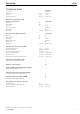
Technical data
PDR 908 HP
Anchoring (B)
Anchoring of Miele Plinths
Miele Plinth installation (fasteners included)
Required anchor points
No.
4
Wood screws according to DIN
571
inch (mm)
8
x 65
Rawl plugs (diameter
x length)
inch (mm)
12
x 60
Plinth floor anchoring (to be provided on site)
Machine installation on on
-site plinth (concrete or masonry)
Min. plinth installation footprint (W/D)
inch (mm)
23 5/8" / 25 9/16"
(600/650)
Wood screws according to DIN
571
inch (mm)
6
x 50
Rawl
plugs (diameter x length)
inch (mm)
8
x 40
Machine data
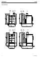
Overall machine dimensions (H/W/D)
inch (mm)
33 7/16" / 23 13/16" /
30 9/16" (850/605/777)
Casing dimensions (H/W/D)
inch (mm)
33 7/16" / 23 7/16" / 29"
(850/596/737)
Site-access dimensions (H/W)
Min. site
-access opening (excl. packaging)
inch (mm)
35 7/16" / 23 13/16"
(900/605)
Installation dimensions
Min. side gap
inch (mm)
13/16" (20)
Recommended side gap
– washer-dryer stack
inch (mm)
11 13/16" (300)
Min. distance to opposite wall from front of machine
inch (mm)
37 3/8" (950)
Recommended distance to opposite wall from front of machine
inch (mm)
43 5/16" (1,100)
Weights and floor loads
Machine weight (net weight)
lb (kg)
161 (73)
Max. floor load in operation
N
925
Emissions
Sound pressure level (in accordance with EN
ISO 11204/11203)
dB(A)
<
70
Heat dissipation rate to installation site
W
37 3/8" (950)