
Installation Plan (Steam)
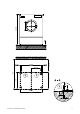


Table Of Contents

Electrical connection must comply with national regulations.
Connection using multi-pole lockable wall socket in
compliance with IEC/EN 60309 and IEC/EN 60947 is
recommended in order to simplify electrical tests. If
machines are hard-wired, a multi-pole mains switch must be
provided on site. Switches with a contact gap of more than
3 mm can be used. These include switches, fuses and
contactors (IEC/EN 60947). A wall socket or mains isolator
must be easily accessible after installation.
Reinstallation of the supply point, changes to the equipment
or checks on the protective conductor, including
determination of correct fuse rating, should only be
performed by a properly trained electrician.
If necessary, equipotential bonding with good galvanic
contact must be provided in accordance with all appropriate
national and local regulations.
Equipotential
bonding
3/8'' x 1 3/8'' 10 mm × 35 mm
Connection with male thread
Connection with washers and nut
M 10
Accessories to be ordered separately
If necessary, equipotential bonding with good galvanic
contact must be provided in accordance with all appropriate
national and local regulations.
Steam
connection
Steam pressure
87 – 145 psi
600 - 1.000 kPa
Boiling point
329 - 363 °F
Steam supply capacity
132 lb/h
Connection thread (on site)
165 – 184 °C
60 kg/h
1/2" internal
thread (NPT)
Steam valve, steam filter and steam stopcock must be
provided on site.
Supply lead steam valve (length). The supply lead for the
electric steam valve is included.
19 11/16'' 500 mm
The steam valve should be installed close to the steam
connection.
Note installation instructions for steam-heated Miele tumble
dryers.
Condensate
connection
Connection thread (on site)
1/2" internal thread
(NPT)
Stopcock and condensate separator to be provided on site.
The condensate drain should be installed such that the
heater banks self-drains when the machine is not in
operation. Consequently, there should be no build-up of
condensate in the heater bank.
The installation of bell-
shaped condensate drai
ns is recommended.
Vented
Max. nominal air flow in vented mode
588 cfm
1000 m³/h
Max. permissible pressure loss
0.04 psi
300 Pa
Connection on machine side (ext. diameter)
5 15/16''
150 mm
Connection pipe provided on site (int. diameter)
5 15/16''
150 mm
Max. temperature
176 °F 80 °C
As relative humidity inside the vent ducting can be as high
as 100 %,
suitable measures must be taken to prevent a
backflow of condensate into the machine.
Air intake
Standard connection: Air intake from installation site
Unobstructed air intake into room recommended
(corresponding to 3 times the vent cross-section of
machine)
83 in² 531 cm²
A sufficient supply of fresh air should be ensured to
replace the air extracted.
Alternative connection: Ducted air intake (from outside
building)
Connector on machine (int. diameter)
6 5/16''
161 mm
Connection pipe provided on site (ext. diameter)
6 5/16''
160 mm
Lid removal exposes live components! For safety reasons,
the pipe connected for central air intake should be at least
35 ½” [900 mm] long and secured using two screws.
Installation plan: PT 8507 D (Steam Heated)
Date: 2015-06-01
Page: 14